


GE Analytical Instruments ©2010
161 of 226
DLM 74001-04 Rev. A
Chapter 8: Troubleshooting
2. Begin by testing the flow of water on the DI water side of the fluidics module. Remove the Masterflex
tubing from the stainless steel tubing connected to the cell. If water is flowing from the stainless steel
tubing, proceed to Step 5. If there is no water flowing from the tubing, proceed to the next step.
3. On the Analyzer’s touch screen, press the
Menu
button, then select
Maintenance
Advanced
Diagnostics
.
4. Press the
Test Pumps
button, and then press the
DI Pump
button. Cycle the pump on and off a few
times, by pressing the
On
and
Off
buttons, finally leaving it set to
On
. If there is no flow, contact GE
Analytical instruments for further assistance. You may need to replace the measurement module.
5. Replace the Masterflex tubing, so it connects to the stainless steel tubing.
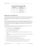
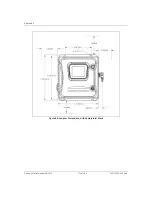
6. Remove the Masterflex tubing from the front solenoid valve and check to see if water is flowing through
the restrictor tubing (see Figure 40).
• If there is water flowing from the restrictor tubing, reconnect the tubing to the solenoid valve. If there
is no water flowing through the restrictor tubing, you may need to replace the restrictor tubing
(available in the 500 RL Tubing Set from GE Analytical Instruments).
Figure 40: Disconnecting the Tubing from the Front Solenoid Valve
7. On the
Test Pumps
screen, press the
Off
button.
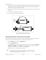
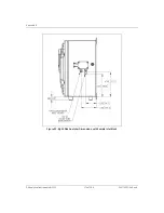
8. Continue by testing the flow of water on the sample water side of the fluidics module. Inside the
Analyzer, swap the inlet and outlet tubing connections (see Figure 41). Connect the inlet fitting to the
waste port and the waste fitting to the inlet port. Loosen each of the Valco fittings and connect them to
the opposite port by tightening 1/4 turn past finger-tight.
Conductivity
Cell Tubing
Summary of Contents for Sievers 500 RL
Page 8: ...GE Analytical Instruments 2010 8 of 226 DLM 74001 04 Rev A ...
Page 10: ...GE Analytical Instruments 2010 10 of 226 DLM 74001 04 Rev A ...
Page 36: ...GE Analytical Instruments 2010 36 of 220 DLM 74001 04 Rev A ...
Page 66: ...GE Analytical Instruments 2010 66 of 226 DLM 74001 04 Rev A Chapter 3 Installation ...
Page 152: ...GE Analytical Instruments 2010 152 of 226 DLM 74001 04 Rev A Chapter 7 Maintenance ...
Page 170: ...GE Analytical Instruments 2010 170 of 226 DLM 74001 04 Rev A Chapter 8 Troubleshooting ...
Page 178: ...Appendix A GE Analytical Instruments 2010 178 of 186 DLM 74001 04 Rev A ...
Page 185: ...Notes GE Analytical Instruments 2010 185 of 186 DLM 74001 04 Rev A 186 ...
Page 186: ...Notes GE Analytical Instruments 2010 186 of 186 DLM 74001 04 Rev A 186 ...