


GE Analytical Instruments ©2010
50 of 226
DLM 74001-04 Rev. A
Chapter 3: Installation
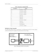
3. The third terminal block (TB3) is for serial and three 4-20 mA analog outputs.
Power isolation level is 240 VAC rms for all terminal blocks, except for the 24 V power (TB2, pins 9 and 10) and the
Reserved pins on all terminal blocks. The maximum load for the alarm ports is 30 VDC at 1.0 A. The maximum 4-
20 mA load is 600 ohms.
* NC = normally closed, NO = normally open
* NC = normally closed, NO = normally open
Table 1: Alarm Outputs (TB2)
Pin Number
Output
10
24 V (ground, for binary input)
9
24 V (+ output, for binary input)
8
Remote -
7
Remote +
6
Alarm 2 (NO*)
5
Alarm 2 (NC*)
4
Alarm 2 (Common)
3
Alarm 1 (NO*)
2
Alarm 1 (NC*)
1
Alarm 1 (Common)
Table 2: Alarm Outputs (TB1)
Pin Number
Output
8
Reserved
7
Reserved
6
Alarm 4 (NO*)
5
Alarm 4 (NC*)
4
Alarm 4 (Common)
3
Alarm 3 (NO*)
2
Alarm 3 (NC*)
1
Alarm 3 (Common)
Summary of Contents for Sievers 500 RL
Page 8: ...GE Analytical Instruments 2010 8 of 226 DLM 74001 04 Rev A ...
Page 10: ...GE Analytical Instruments 2010 10 of 226 DLM 74001 04 Rev A ...
Page 36: ...GE Analytical Instruments 2010 36 of 220 DLM 74001 04 Rev A ...
Page 66: ...GE Analytical Instruments 2010 66 of 226 DLM 74001 04 Rev A Chapter 3 Installation ...
Page 152: ...GE Analytical Instruments 2010 152 of 226 DLM 74001 04 Rev A Chapter 7 Maintenance ...
Page 170: ...GE Analytical Instruments 2010 170 of 226 DLM 74001 04 Rev A Chapter 8 Troubleshooting ...
Page 178: ...Appendix A GE Analytical Instruments 2010 178 of 186 DLM 74001 04 Rev A ...
Page 185: ...Notes GE Analytical Instruments 2010 185 of 186 DLM 74001 04 Rev A 186 ...
Page 186: ...Notes GE Analytical Instruments 2010 186 of 186 DLM 74001 04 Rev A 186 ...