


GE Analytical Instruments ©2010
143 of 226
DLM 74001-04 Rev. A
Chapter 7: Maintenance
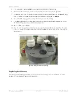
9. Slide the nut up the lamp housing (toward the connector cord), and then slide the ferrules up the lamp
housing, until they are level with the black heat shrink tubing. Be careful when inserting the lamp into
the Analyzer as the nut and ferrules may slide off. Refer to Figure 34 and Figure 35 for proper
orientation of the ferrules.
Figure 34: Relative Positioning of Components in the UV Lamp Assembly
Figure 35: UV Lamp Ferrule Orientation Detail
10. Carefully slide the lamp assembly into the enclosure. Stop if you feel any resistance, and realign the
lamp in the reactor. Make sure the black heat tubing is flush against the brass-colored nut.
11. Tighten the brass-colored nut finger-tight. While tightening the nut, make sure the heat shrink tubing
remains flush against the nut (Figure 34). Do
not
use a wrench.
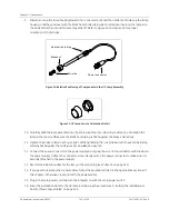
12. Connect the power connector to the power supply by aligning the slot on the connector with the slot on
the power supply. Tighten the connector screw. Gently pull on the power connector to make sure it is
securely attached to the power supply.
13. Record the installation date for the lamp in the service log (see Table 15 on page 151).
14. If you need to replace other consumables, follow the procedures listed in the appropriate sections of
this chapter. Otherwise, close and latch the Analyzer door.
15. Plug in the main power cord and turn the Analyzer on with the main power switch.
16. Enter the installation date for the UV lamp by following the procedures in “Setting the Installation or
Date for New Consumables” on page 149.
Heat shrink t ubing
Brass nut
Ferrules
Pow er connect or
Summary of Contents for Sievers 500 RL
Page 8: ...GE Analytical Instruments 2010 8 of 226 DLM 74001 04 Rev A ...
Page 10: ...GE Analytical Instruments 2010 10 of 226 DLM 74001 04 Rev A ...
Page 36: ...GE Analytical Instruments 2010 36 of 220 DLM 74001 04 Rev A ...
Page 66: ...GE Analytical Instruments 2010 66 of 226 DLM 74001 04 Rev A Chapter 3 Installation ...
Page 152: ...GE Analytical Instruments 2010 152 of 226 DLM 74001 04 Rev A Chapter 7 Maintenance ...
Page 170: ...GE Analytical Instruments 2010 170 of 226 DLM 74001 04 Rev A Chapter 8 Troubleshooting ...
Page 178: ...Appendix A GE Analytical Instruments 2010 178 of 186 DLM 74001 04 Rev A ...
Page 185: ...Notes GE Analytical Instruments 2010 185 of 186 DLM 74001 04 Rev A 186 ...
Page 186: ...Notes GE Analytical Instruments 2010 186 of 186 DLM 74001 04 Rev A 186 ...