MB95630H Series
MN702-00009-1v0-E
FUJITSU SEMICONDUCTOR LIMITED
365
CHAPTER 20 16-BIT RELOAD TIMER
20.6 Operations and Setting Procedure Example
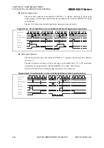
Figure 20.6-5 Count Operation in Reload Mode (External Gate Input Operation)
■
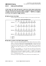
Operation of Internal Clock Mode (One-shot Mode)
When the count enable bit (CNTE) is set to "1" and the software trigger bit (TRG) is set to "1"
or the valid edge (rising, falling or both edges selectable) specified by the operating mode
select bits (MOD[2:0]) is input to the TIn pin, the value set in the 16-bit reload timer reload
register is reloaded to the 16-bit downcounter and down-counting starts. When the count enable
bit (CNTE) and software trigger bit (TRG) are set to "1" at the same time and then counting is
enabled, the count is started simultaneously.
If the reload select bit (RELD) is "0", the 16-bit counter halts at "0xFFFF" when the 16-bit
counter underflows ("0x0000"
→
"0xFFFF"). In this case, the underflow interrupt request flag
bit (UF) is set to "1" and if the underflow interrupt request enable bit (INTE) is "1", an
interrupt request is output.
A square waveform can be output from the TOn pin to indicate that the count is in progress.
●
Software trigger operation
The count starts when the count enable bit (CNTE) is "1" and the software trigger bit (TRG) is
set to "1".
Figure 20.6-6 shows the software trigger operation in one-shot mode.
Figure 20.6-6 Count Operation in One-shot Mode (Software Trigger Operation)
Co
u
nt clock
Co
u
nter
-1
0000
-1
D
a
t
a
lo
a
d
s
ign
a
l
UF
b
it
CNTE
b
it
TIn pin
TOn pin
Relo
a
d d
a
t
a
Relo
a
d d
a
t
a
TRG
b
it
-1
-1
-1
Co
u
nt clock
Co
u
nter
-1
0000
-1
0000
D
a
t
a
lo
a
d
s
ign
a
l
UF
b
it
CNTE
b
it
TRG
b
it
TOn pin
Relo
a
d d
a
t
a
Relo
a
d d
a
t
a
FFFF
FFFF
W
a
it for
s
t
a
rt trigger inp
u
t

