MB95630H Series
MN702-00009-1v0-E
FUJITSU SEMICONDUCTOR LIMITED
177
CHAPTER 12 EXTERNAL INTERRUPT CIRCUIT
12.2 Configuration
12.2
Configuration
The external interrupt circuit consists of the following blocks:
• Edge detection circuit
• External interrupt control register
■
Block Diagram of External Interrupt Circuit
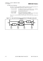
Figure 12.2-1 is the block diagram of the external interrupt circuit.
Figure 12.2-1 Block Diagram of External Interrupt Circuit
●
Edge detection circuit
When the polarity of the edge detected on a signal input to an external interrupt circuit pin
(INT) matches the polarity of the edge selected in the interrupt control register (EIC), a
corresponding external interrupt request flag bit (EIR) is set to "1".
●
External interrupt control register (EIC)
This register is used to select an edge, enable or disable interrupt requests, check for interrupt
requests, etc.
EIR1
S
L11
S
L10
EIE1
EIR0
S
L01
S
L00
EIE0
Extern
a
l interr
u
pt
control regi
s
ter
(EIC)
Note: Pin n
a
me
s
a
nd interr
u
pt re
qu
e
s
t n
u
m
b
er
s
v
a
ry
a
mong prod
u
ct
s
.
For det
a
il
s
, refer to “
■
PIN FUNCTION
S
”
a
nd “
■
INTERRUPT
S
OURCE TABLE”
in the device d
a
t
a
s
heet.
INTn
Pin
INTn+1
Pin
10
01
11
S
elector
10
01
11
S
elector
IRQXX
IRQXX
Inter
n
a
l d
a
t
a
bu
s
Edge detection circ
u
it 0
Edge detection circ
u
it 1


