MB95630H Series
510
FUJITSU SEMICONDUCTOR LIMITED
MN702-00009-1v0-E
CHAPTER 24 I
2
C BUS INTERFACE
24.6 Operations and Setting Procedure Example
The following sample flow chart illustrates the procedure:
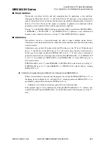
Figure 24.6-5 Sample Flow Chart 1
●
Example of generating an interrupt (IBCR1n:INT = 1) with "IBCR0n:ALF = 1" detected
If a START condition is generated by the program (by setting the IBCR1n:MSS bit to "1")
with the bus busy (IBSRn:BB = 1) and arbitration lost detected, a IBCR1n:INT bit interrupt
occurs upon detection of "IBCR0n:ALF = 1".
Figure 24.6-6 Timing Diagram with Interrupt Generated with "IBCR0n:ALF = 1" Detected
S
et m
as
ter mode.
S
et the M
SS
b
it in I
2
C
bus
control regi
s
ter 1 (IBCR1n) to "1".
En
ab
le AL interr
u
pt
s
(IBCR0n:ALE =1).
IBCR0n:ALF = 1
IB
S
Rn:BB = 0
YE
S
YE
S
NO
NO
Norm
a
l control
Write "0" to IBCR0n:ALF to
cle
a
r AL fl
a
g
a
nd interr
u
pt.
Write "0" to IBCR0n:ALE to
cle
a
r AL interr
u
pt.
D
a
t
a
S
l
a
ve
a
ddre
ss
S
TART condition
Interr
u
pt in 9th clock cycle
S
CLn pin
S
DAn pin
ICCRn:EN
IBCR1n:M
SS
IBCR0n:ALF
IB
S
Rn:BB
IBCR1n:INT
Cle
a
r IBCR0n:ALF
b
y
s
oftw
a
re.
Cle
a
r IBCR1n:INT
b
y
s
oftw
a
re
a
nd rele
as
e
S
CLn line.
ACK


