MB95630H Series
232
FUJITSU SEMICONDUCTOR LIMITED
MN702-00009-1v0-E
CHAPTER 14 LIN-UART
14.6 Operations of LIN-UART and LIN-UART
Setting Procedure Example
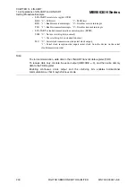
Find the baud rate setting with the following equations.
When the counter of the 8/16-bit composite timer does not overflow
: BGR value = (b - a) / 8 - 1
When the counter of the 8/16-bit composite timer has overflowed
: BGR value = (max + b - a) / 8 - 1
max: Maximum value of free-run timer
a: TII0 data register value after the first interrupt
b: TII0 data register value after the second interrupt
Note:
If the BGR value newly calculated based on the synch field in LIN slave mode as
explained above has an error of
±
15
%
or more, do not set the baud rate.
For the operations of the input capture function of the 8/16-bit composite timer, see "11.12
Operation of Input Capture Function".
●
LIN synch break detection interrupt and flag
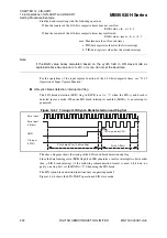
The LIN break detection (LBD) flag in ESCR is set to "1" when the LIN synch break is
detected in slave mode. When the LIN break interrupt is enabled (LBIE = 1), an interrupt is
generated.
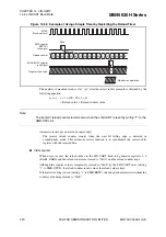
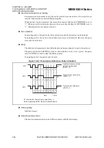
Figure 14.6-7 Timing of LIN Synch Break Detection and Flag Set
The above diagram shows the timing of the LIN synch break detection and flag.
Since the data framing error (FRE) flag bit in SSR generates a receive interrupt two bits earlier
than a LIN break interrupt (if the following communication format is used: 8-bit data, no
parity, one stop bit.), set the RXE to "0" when using the LIN break.
The LIN synch break detection functions only in operating mode 3.
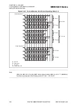
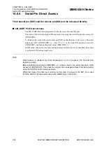
Figure 14.6-8 shows the LIN-UART operation in LIN slave mode.
LBD
S
ynch field
S
eri
a
l clock
S
eri
a
l inp
u
t
(LIN
bus
)
TII0 inp
u
t
(L
S
YN)
LBD cle
a
red
b
y CPU
S
ynch
b
re
a
k (for 14
b
it
s
s
etting)


