MB95630H Series
MN702-00009-1v0-E
FUJITSU SEMICONDUCTOR LIMITED
233
CHAPTER 14 LIN-UART
14.6 Operations of LIN-UART and LIN-UART
Setting Procedure Example
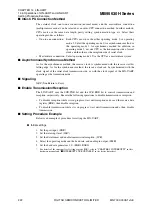
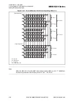
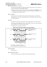
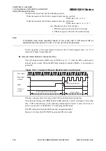
Figure 14.6-8 LIN-UART Operation in LIN Slave Mode
●
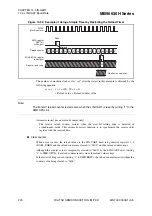
LIN bus timing
Figure 14.6-9 LIN Bus Timing and LIN-UART Signals
FRE
(RXE = 1)
LBD
(RXE = 0)
S
eri
a
l clock cycle#
S
eri
a
l clock
S
eri
a
l inp
u
t
(LIN
bus
)
Receive interr
u
pt gener
a
ted when RXE = 1
Receive interr
u
pt gener
a
ted when RXE = 0
0
1
2
3
4
5
6
7
8
9 10 11 12 1
3
14 15
bus
RXE
LBD
(IRQ)
RDRF
(
S
IN)
(IRQ)
IRQ(TII0)
LIN
LBIE
RIE
8
/16-
b
it compo
s
ite timer co
u
nt
No clock
(C
a
lc
u
l
a
tion fr
a
me)
Previo
us
s
eri
a
l clock
Newly c
a
lc
u
l
a
ted
s
eri
a
l clock
En
ab
le receive
interr
u
pt
s
LIN
b
re
a
k
s
t
a
rt
s
LIN
b
re
a
k detected, interr
u
pt gener
a
ted
IRQ cle
a
r
b
y CPU (LBD
→
0)
IRQ cle
a
r: inp
u
t c
a
pt
u
re of
8
/16-
b
it compo
s
ite timer co
u
nt
s
t
a
rt
s
IRQ cle
a
r: B
au
d r
a
te c
a
lc
u
l
a
ted
a
nd
s
et
LBIE di
sab
led
Reception en
ab
led
F
a
lling edge of
s
t
a
rt
b
it
1
b
yte of reception d
a
t
a
sa
ved to RDR
RDR re
a
d
b
y CPU
RDR re
a
d
b
y CPU
TII0 inp
u
t
(L
S
YN)
IRQ (
8
/16-
b
it compo
s
ite timer)
IRQ (
8
/16-
b
it compo
s
ite timer)

