MB95630H Series
260
FUJITSU SEMICONDUCTOR LIMITED
MN702-00009-1v0-E
CHAPTER 14 LIN-UART
14.8 Notes on Using LIN-UART
●
Synch break detection
In operating mode 3 (LIN mode), when serial input is 11 bits or more in width and becomes
"L", the LBD bit in the extended status control register (ESCR) is set to "1" (synch break
detected) and the LIN-UART waits for the synch field. Therefore, when serial input has more
than 11 bits of "0" not at the time of a synch break, the LIN-UART recognizes that a synch
break has been input (LBD = 1) and then waits for the synch field.
In this case, execute the LIN-UART reset (SMR: UPCL = 1).
●
Handling framing errors
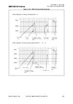
If a framing error occurs (stop bit:SIN = 0) and the next start bit (SIN = 0) immediately follows
it, this start bit is recognized regardless of a falling edge for the start bit and reception is
started. This sequence is used for detecting the continuous "L" state of the serial data input
(SIN) when the next framing error is detected while the data stream is synchronized (See
"When reception is always enabled (RXE = 1)" in Figure 14.8-1).
If this operation is not necessary, disable data reception temporarily after receiving a framing
error (RXE = 1
→
0
→
1). Therefore, the falling edge of the serial data input (SIN) is detected,
the start bit is recognized when "L" is detected at the reception sampling point, and the
reception is started (See "When reception is temporarily disabled (RXE = 1
→
0
→
1)" in


