MB95630H Series
252
FUJITSU SEMICONDUCTOR LIMITED
MN702-00009-1v0-E
CHAPTER 14 LIN-UART
14.7 Registers
14.7.5
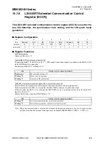
LIN-UART Extended Status Control Register
(ESCR)
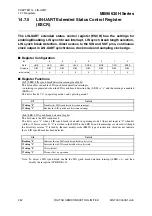
The LIN-UART extended status control register (ESCR) has the settings for
enabling/disabling LIN synch break interrupt, LIN synch break length selection,
LIN synch break detection, direct access to the SIN and SOT pins, continuous
clock output in LIN-UART synchronous clock mode and sampling clock edge.
■
Register Configuration
■
Register Functions
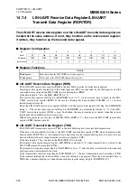
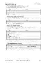
[bit7] LBIE: LIN synch break detection interrupt enable bit
This bit enables or disables LIN synch break detection interrupts.
An interrupt is generated when the LIN synch break detection flag (LBD) is "1" and the interrupt is enabled
(LBIE = 1).
This bit is fixed at "0" in operating mode 1 and operating mode 2.
[bit6] LBD: LIN synch break detection flag bit
This bit detects the LIN synch break.
This bit is set to "1" when a LIN synch break is detected in operating mode 3 (the serial input is "0" when bit
width is 11 bits or more). If "0" is written to the LBD bit, the LBD bit and the interrupt are cleared. Although
the bit always returns "1" if read by the read-modify-write (RMW) type of instruction, this does not indicate
that a LIN synch break has been detected.
Note: To detect a LIN synch break, enable the LIN synch break detection interrupt (LBIE = 1), and then
disable the reception (SCR:RXE = 0).
bit
7
6
5
4
3
2
1
0
Field
LBIE
LBD
LBL1
LBL0
SOPE
SIOP
CCO
SCES
Attribute
R/W
R/W
R/W
R/W
R/W
R/W
R/W
R/W
Initial value
0
0
0
0
0
1
0
0
bit7
Details
Writing "0"
Disables the LIN synch break detection interrupt.
Writing "1"
Enables the LIN synch break detection interrupt.
bit6
Details
Reading "0"
Indicates that no LIN synch break has been detected.
Writing "1"
Indicates that a LIN synch break has been detected.
Writing "0"
Clears this bit.
Writing "1"
Has no effect on operation.


