


[email protected]
whatsapp:959440045
6
Dismantling & Assembly
6.1
Inlet/outlet and bowl
G0887751
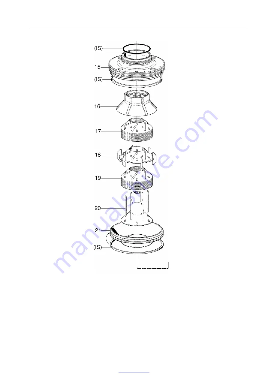
15. Bowl hood
16. Top disc
17. Bowl discs
18. Wing insert
19. Bowl discs
20. Distributor
21. Sliding bowl bottom
89
www.fdm.com.pe
[email protected]
whatsapp:959440045
6
Dismantling & Assembly
6.1
Inlet/outlet and bowl
G0887751
15. Bowl hood
16. Top disc
17. Bowl discs
18. Wing insert
19. Bowl discs
20. Distributor
21. Sliding bowl bottom
89
www.fdm.com.pe