Fayat Dynapac F80W Operating Manual Download Page 168

162

F80W

D451143

6

5

D451144

9

8

7

D451126

1

2

D451127A

3

4

3.6  Lubrication and maintenance operations

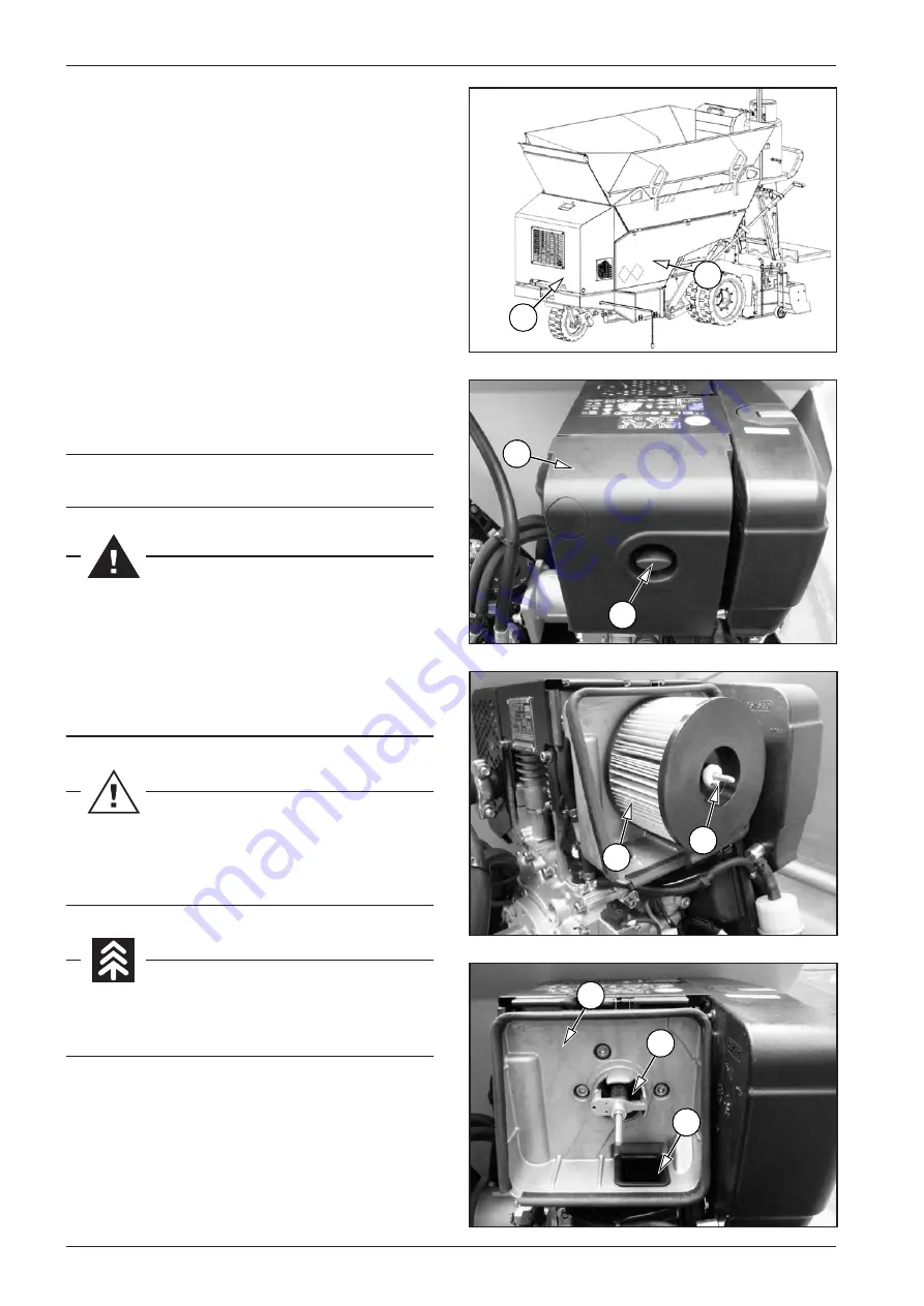
3.6.24  Air filter replacement

Perform air filter replacement when the machine is parked on 

a flat and solid surface with the engine and battery disconnecter 

off.

Air filter replacement procedure:

•  Open the left material hopper side cover (1).
•  Open the engine bonnet (2).
•  Unlock the air filter cap (3) and remove the inlet air filter 

cover (4).

•  Remove the nut (5) and the air filter (6).
•  Tighten the inlet openings (7) and (8) are free of dirt and for-

eign objects. 

•  Clean the air filter body (9) and the air filter cover (4). 
•  Mount a new air filter (6) and screw the nut (5). 
•  Mount the air filter cover (4) ad lock the air filter cap (3).

Air filter


Order number: 4812088419

Perform air filter replacement when the machine is 

parked on a flat and solid surface with the engine and 

battery disconnecter off.
When replacing the air filter, use the prescribed protec-

tive equipment.
There is a risk of burns from the hot parts of the engine.

Do not use compressed air to clean the air filter body and 

cover; there is a risk of ingress of foreign objects to suc-

tion holes of air inlets.

Hand over the dismounted air filter for disposal accord-

ing to the national regulations. 

Summary of Contents for Dynapac F80W

Page 1: ...OPERATING MANUAL Asphalt paver wheeled F80W Hatz 4812217930 ...

Page 2: ......

Page 3: ...F80W Asphalt paver wheeled Hatz Tier 4 final Operating Manual Edition 04 2018 EN From Serial No 4510023 Original Operating Manual ...

Page 4: ......

Page 5: ... e d d n u s r e l l e t s r E s e d n o i t i s o P d n u e m a N d n u g n u l l e t s r E r u z e g a r f n A n e h c i l d r ö h e b n e t e d n ü r g e b r e n i e i e b e i d r e g a n a M l a r e n e G Vorlage des entsprechenden Abschnitts der technischen Unterlagen berechtigt ist s r e l l e t s r E s e d t f i r h c s r e t n U Wardenburg 19 09 2018 g n u l l e t s r E r e d m u t a D d n...

Page 6: ......

Page 7: ...eration of the machine and provide them information for maintenance Therefore it is necessary to pass this manual to operators and ensure that it will be read by them carefully before the road roller is used DYNAPAC assumes no responsibility in cases when the machine is operated incorrectly or is used incorrectly in operating modes which may result in an injury or death damage to the machine or pr...

Page 8: ... modifications of figures are reserved All dimensions and weights are approximate and therefore not binding DYNAPAC reserves the right to perform modifications at any time with no obligation to inform the machine user If you identify any differences between the machine operated by you and the information contained in this publication contact your local dealer Reproduction or copying of any kind is...

Page 9: ... personal hazards The notice warns of possible damage to the machine or its parts The notice warns of the necessity of environmental protection CAUTION As used in this operating manual the terms right left front and rear indicate sides of the machine moving forward REAR TOP DOWN FRONT LEFT RIGHT DOWN TOP ...

Page 10: ...screed operator stand during machine operation 34 2 1 7 Dangerous zone and safe distance 35 2 1 8 Machine operation at unclear working areas 38 2 1 9 Manual signals 38 2 1 10 Safety notices and symbols used on the machine 42 2 1 11 Personal protective equipment 45 2 1 12 General safety precautions 46 2 1 13 Safety precautions during machine operation 46 2 1 14 Safety and fire precautions during th...

Page 11: ...Using and setting the paving direction indicator 88 2 5 15 Hopper 89 2 5 16 Material outlet 90 2 5 17 Conveyor 91 2 5 18 Conveyor limit switch 92 2 5 19 Augers 93 2 6 Operation of the screed 94 2 6 1 Lifting and lowering the screed 94 2 6 2 Screed lock 95 2 6 3 Setting the paving width 96 2 6 4 Setting the paving thickness 98 2 6 5 Setting the roadway profile 99 2 6 6 Setting the end gates 100 2 6...

Page 12: ...symbols specified in maintenance plans 127 3 4 Lubrication and maintenance chart 128 3 5 Lubrication and service plan 130 3 5 1 Maintenance plan 130 3 6 Lubrication and maintenance operations 131 Every 10 hours at the beginning of work daily 132 3 6 1 Fuel level check 132 3 6 2 Engine oil check 133 3 6 3 Hydraulic oil check in the hydraulic tank 134 3 6 4 Driver s stand cleaning 135 3 6 5 Cleaning...

Page 13: ... Gas line hose replacement 168 Maintenance as required 169 3 6 29 Battery replacement 169 3 6 30 Screw connections tightness check 170 3 7 Troubleshooting 172 3 7 1 Troubleshooting 172 3 7 2 Troubleshooting engine faults when indicator lamps are lit on the display 172 3 7 3 Troubleshooting the hydraulic system 172 3 7 4 Troubleshooting the electrical system 173 3 7 5 Troubleshooting of screed heat...

Page 14: ...8 F80W ...

Page 15: ...9 F80W SPECIFICATION MANUAL 1 SPECIFICATION MANUAL F80W Hatz Tier 4 Final ...

Page 16: ...ption The F80W wheeled asphalt paver is equipped with a screed with gas heating The basic paving width is from 800 mm 31 5 in to 1 300 mm 51 2 in The machine is characterised with good manoeuvrability good view from the operator s place a wide range of uses and easy transport Specification of the expected use of the machine The performance and dimensions of the F80W wheeled asphalt paver predeterm...

Page 17: ...D451023 AMMERLAENDER STR 93 D 26203 WARDENBURG GERMANY D451024 D451025 SPECIFICATION MANUAL Nameplate Serial number of the machine Nameplate of the screed Serial number of the screed Serial number of the engine ...

Page 18: ...12 F80W W1 W2 W W3 W4 B L L1 H H1 D451170A A L2 1 2 Dimensional drawing of the machine ...

Page 19: ...13 F80W SPECIFICATION MANUAL A B H H1 L L1 mm 1280 2070 2680 1598 2865 2526 in 50 4 81 5 105 5 62 9 112 8 99 4 L2 W W1 W2 W3 W4 mm 2550 765 640 800 1150 1699 in 100 4 30 1 25 2 31 5 45 3 66 9 ...

Page 20: ...nt with a full hopper screed in the lower position 20 36 Lateral static stability with an empty hopper 12 21 Lateral static stability with a full hopper 12 21 Drive type Hydrostatic Number of driving axles 1 Steering Steering type Hydraulic Steering control Hydraulic servo unit Engine Manufacturer Hatz Type 1B40T Power according to ISO 3046 1 kW HP 6 3 8 Number of cylinders 1 Cylinder capacity cm3...

Page 21: ... machine mm in 1 300 51 2 Minimum paving width with reduction plates mm in 250 9 8 Maximum paving width with reduction plates mm in 750 29 5 Minimum paving width with mechanical extension mm in 1 150 45 3 Maximum paving width with mechanical extension mm in 1 650 65 Electrical installation Voltage V 12 Battery capacity Ah 55 Noise and vibration emissions Measured sound power level A LpA at the ope...

Page 22: ...ty with a full hopper screed in the lower po sition Machine descent with an empty hopper screed in the lower position Machine descent with a full hopper screed in the lower posi tion 1 3 2 Machine gradeability and lateral static stability Machine gradeability with an empty hopper screed in the lower position ...

Page 23: ...17 F80W D451175 α 12 21 SPECIFICATION MANUAL Lateral static stability with an empty and full hopper ...

Page 24: ...t Order number 1 4 2 Screed vibration units 4812061026 1 4 3 Mechanical screed extension 4812061017 1 4 4 Dual wheels 4812061018 1 4 5 Front wheel scraper 4812061021 1 4 6 Material hopper extension 4812061019 1 4 7 Additional lighting 4812061020 1 4 Optional equipment ...

Page 25: ...chine trav el forward The vibration unit switch 6 is located on the left from the dash board and the screed vibration indicator lamp 30 is located on the display of the dashboard Turning on Turn the vibration unit switch 6 on the main dashboard to the upper position During the machine travel forward the vibration function is ac tivated and the screed vibration indicator lamp 30 turns on When the m...

Page 26: ...sion 1150 mm 45 3 in Maximum paving width with mechanical extension 1650 mm 65 in Mount the mechanical screed extension according to the Mounting Manual Mechanical screed extension kit Order number 4812061017 The mechanical screed extension kit consists of the follow ing components Mechanical screed extension left 1 Mechanical screed extension right 2 Auger extension left 3 Auger extension right 4...

Page 27: ...elease the paving width switch 3 lock it back to the middle position and the screed stops in the required position To decrease the paving width on the right side turn the paving width switch 3 to the left and hold it To release the paving width switch 3 lock it back to the middle position and the screed stops in the required position Check the required setting of the paving width on the right side...

Page 28: ...s With standard rear wheels 765 mm 30 1 in With dual wheels 1 077 mm 42 4 in Mount the dual wheels according to the Mounting Manual Dual wheel kit Order number 4812061018 The dual wheel kit consists of the following components Two dual wheels 1 Two dual wheel supports 2 Two dual wheel cover plates 3 Mounting material During mounting of dual wheels the machine must be parked on a flat and solid sur...

Page 29: ...scraper kit Order no 4812061021 The front wheel scraper kit consists of the following com ponents Front wheel scraper 1 Mounting material Operating the front wheel scraper The distance of the scraper to the front wheel can be adjusted by loosening the screws 2 on both sides During mounting of front wheel scraper the machine must be parked on a flat and solid surface with the en gine and battery di...

Page 30: ...material hopper extensions according to the Mounting Manual Material hopper extension kit Order number 4812061019 The material hopper extension kit consists of the following components Material hopper extension left 2 Material hopper extension right 1 During mounting of the material hopper extension the machine must be parked on a flat and solid surface with the engine and battery disconnecter off...

Page 31: ...2061020 The additional lighting kit consists of the following compo nents Additional lighting 1 Mounting material Operating the additional lighting The additional lighting is fitted with its own switch on the rear of the light which is used to switch the light on and off During mounting of additional lighting the machine must be parked on a flat and solid surface with the en gine and battery disco...

Page 32: ...26 F80W Notes ...

Page 33: ...27 F80W SPECIFICATION MANUAL Notes ...

Page 34: ...28 F80W ...

Page 35: ...29 F80W OPERATING MANUAL 2 OPERATING MANUAL F80W Hatz Tier 4 Final ...

Page 36: ...ctive authorised workers any and all information for the safe use of electric installations and electronic equipment of the machine always in compliance with respective national regulations He must ensure and hand over to respective authorised work ers any and all information for the safe use and handling of gas bottles if they form part of the equipment during the operation of the machine always ...

Page 37: ...machine Professional knowledge of procedures for handling and use of gas bottles Professional knowledge of procedures in case of fire and extinguishing the machine equipped with a gas bottle Professional knowledge of procedures for the use of the prescribed fire extinguisher Professional knowledge of procedures for first aid provision in case of gas leakage from the system and subsequent harm to p...

Page 38: ...e in zero positions and no persons are allowed to stay in the danger zone of the machine Always before starting the engine the driver is obliged to notify others by means of a sound signal each time the machine is put into operation Before putting the machine into operation the driver must check the brakes and steering for functioning After a warning alarm the operator may put the machine into ope...

Page 39: ... previous work shift Before starting the work the screed operator is obliged to in spect the machine and accessories and to check control ele ments and communication and safety equipment for function ing according to the manual When he finds a defect that might endanger the safety of work and is not able to repair it then he must not put the machine into operation and must report the defect to a r...

Page 40: ... during ma chine operation DYNAPAC assumes no responsibility in cases when the machine is operated incorrectly or is used incorrectly in operating modes which may result in an injury or death damage to the machine or property During machine operation no objects may be located on the driver s stand Operation of the machine during paving at a workplace The driver s stand during machine travel and pa...

Page 41: ...fessionally qualified instructed and trained personnel authorised to operate and maintain the machine During the operation of the machine and paving no people may be present and stay in the dangerous zone of the machine The machine user as well as the machine operator must ensure adherence to the prohibition to enter the dangerous zone of the machine during its operation These requirements during ...

Page 42: ...ruction site must be marked with a visible barrier against unauthorised access of other people to the place of paving and construction site The safe distance between a public road the place of paving and the construction site is determined by the machine user on the basis of respective national regulations Observe the safe distance between a public road the place of paving and the construction sit...

Page 43: ...place of paving moving near the machine but not directly operating the machine must observe the mini mum safe distance of 5 metres from the machine The machine user as well as the machine operator must ensure adherence to the aforementioned safe distance of 5 m from the machine with regard to safety of workers at the place of paving ...

Page 44: ...ual signals The machine operator may not operate the machine if he does not have a sufficient overview of the workplace and potential obstacles are not clearly visible In such cases a different efficient form of connection between the appointed worker and the machine operator must be ensured To ensure connection between the appointed worker and the machine operator we recommend using hand signals ...

Page 45: ...39 F80W 0031 STOP 0032 0040 0041 OPERATING MANUAL Stop Watch out Turn off the engine EXAMPLES OF HAND SIGNALS Start the engine ...

Page 46: ...40 F80W 0033 0034 0036 0035 2 1 Main safety precautions Watch out danger Machine travel Drive slowly backward away from me Drive slowly forward towards me ...

Page 47: ...41 F80W 0039 0037 0038 OPERATING MANUAL Machine travel for a short distance Machine travel to the right Machine travel to the left ...

Page 48: ...42 F80W D451034B 2 3 14 15 9 15 14 20 12 16 19 13 14 15 9 15 17 14 1 20 2 18 20 4 10 5 7 6 12 12 11 1 8 12 21 2 1 Main safety precautions 2 1 10 Safety notices and symbols used on the machine ...

Page 49: ...distance from very hot parts Before per forming work wait until the parts cool down 6 Danger of injury and accident by squeezing during screed movement 0026 There is a danger of injury and accident by squeezing dur ing screed movement Never come close to the screed when it moves Keep the prescribed and safe distance from the screed of the machine 7 Risk of burns from hot surfaces 0026a Maintain th...

Page 50: ...dB WA L 3567 104 External noise of the machine 18 Fire extinguisher 5 107016005 Mounting place for a manual fire extinguisher Always have a manual fire extinguisher ready on the driver s stand Perform maintenance of the manual fire extinguisher in prescribed intervals Immediately replace any damaged or depleted manual fire extinguisher 19 First aid kit 2427bz Identification of the place for deposi...

Page 51: ...n and maintenance of the machine 1 0001 Wear work clothes antistatic protective clothes 2 0008 Wear work shoes antistatic protective shoes 3 0030 Wear a warning vest 4 0007 Use a protective helmet 5 0002 Use hearing protection 6 0004 Use a dust protection mask with a filter against organic gases and vapours type A AX 7 0005 Use safety glasses or a safety shield 8 0003 Use protective gloves suitabl...

Page 52: ...check all safety devices on the machine for proper opera tion check performance of all tasks of the regular maintenance remove all dirt from the machine check the whole machine and all additional equipment for correct operation and functioning check the control elements and brakes for correct function ing if you detect any problem during inspection before starting to work inform the machine user I...

Page 53: ... of gas leakage inform relevant national author ities Propane butane LPG is an extremely flammable substance and any leakage causes a high risk of fire or explosion Propane butane LPG is heavier than air and may accumulate in lower situated places danger of fire Gas inhalation may cause headache weakness confusion dizziness and nausea It causes frostbites in the liquid state in contact with skin A...

Page 54: ...3A 113B C A portable fire extinguisher does not form part of delivery of the machine Equip the machine with a portable fire extinguisher according to the national regulations and mount it to the desig nated place at the driver s stand Regularly review how to operate the portable fire extinguisher Operating instructions for the fire extinguisher are given on the fire extinguisher Replace the fire e...

Page 55: ...ry or death damage to the machine property or environment Safety precautions Electrical installations and wiring must be connected properly and according to data given in this Operating Manual Entire electrical wiring and connection components must be have adequate current rating within the meaning of valid regu lations and they must meet requirements of respective national regulations All devices...

Page 56: ...eave the operator stand during operation of the machine The machine operator may not operate the machine if he does not have a sufficient overview of the workplace and potential obstacles are not clearly visible In such cases a different efficient form of connection between the ap pointed worker and the machine operator must be ensured To ensure connection between the appointed worker and the mach...

Page 57: ...sure non adherent surface of the hopper area Prohibited activities during repairs and maintenance of the machine Performing maintenance cleaning and repairs without per sonal protective equipment Performing maintenance cleaning or repairs with the ma chine not secured against spontaneous movement or acci dental start and if a person can come in contact with mov ing parts of the machine Failing to ...

Page 58: ...b the cab must be locked to prevent the machine from operating The key must not be in the ignition box of the machine and the battery disconnecter must be in the position OFF Terminals of the battery must be disconnected The electrolyte level must correspond to recommendations of the manufactur er If the machine is stored for a time interval longer than 2 months the batteries must be removed from ...

Page 59: ...orking position protective covers of the individual instruments and machine covers must be locked if the machine is equipped with a gas bottle the gas bottle must be removed from the machine and stored in a special area Then it is recommended to perform the following tasks repair damaged paintwork service lubrication points according to instructions stated in the manual check the pressure in tyres...

Page 60: ...tanks are drained if they are on the ma chine check that the coolant has the desired antifreeze properties remove the batteries from the machine recharge them ac cording to instructions of the manufacturer and store them in special areas apply chemical preservatives on chromium plated surfaces of piston rods we recommend you to protect the machine from corrosion by applying a chemical preservative...

Page 61: ... bottle on the machine Then it is recommended to perform the following tasks service lubrication points according to instructions stated in the manual check the tyres for pressure if the machine is equipped with wheels check that the coolant has the desired antifreeze properties mount the batteries on the machine recharge them accord ing to instructions of the manufacturer clean the chromium plate...

Page 62: ...56 F80W ...

Page 63: ...e disposal regulations and environment protection regulations Therefore we recommend you in such cases to always contact businesses specialising professionally in waste disposal DYNAPAC does not assume any liability in cases when the machine after its lifetime expires is disposed of in an improper way which may result in damage to the prop erty or environment 2 3 Machine disposal ...

Page 64: ...58 F80W D451032B 26 24 25 35 23 1 5 8 9 27 34 10 11 12 17 18 19 20 29 28 32 31 33 22 7 3 4 13 21 6 14 15 16 3 2 2 30 1 36 2 4 Machine description ...

Page 65: ... 4 2 14 Steering wheel 15 Tow point 16 Paving direction indicator 17 Battery disconnecter 18 Conveyor hydraulic motor 19 Battery 20 Screed linear hydraulic motor 21 Material outlet 22 Hydraulic pumps 23 Beacon 24 Gas bottle 25 Fuse box 26 Warning horn 27 Air filter 28 Fuel tank 29 Bonnet 30 Hydraulic tank 31 Lug for towing the machine 32 Conveyor tensioner 33 Combined cooler 34 Storage space for t...

Page 66: ...60 F80W 451033B 41 41 42 41 37 37 47 47 45 45 46 43 44 38 39 40 40 46 39 51 52 D451032C 48 49 50 2 4 Machine description ...

Page 67: ...ibrators 41 Gas components 42 Fixed frame 43 Left hydraulic extension 44 Main screed right frame 45 Screed tow arm 46 Mechanical extension 47 Paving thickness controller 48 Foot switch 49 Hopper cover 50 Conveyor limit switch 51 Left indicator of paving width setting 52 Right indicator of paving width setting ...

Page 68: ...eering wheel 6 Vibration unit switch optional equipment 7 Safety cover 8 Travel controller 9 Mounting socket 12 V 10 Engine speed adjusting controller 11 Ignition box 12 Warning horn 13 Screed heating switch 14 Paving speed selector 15 Transport operating mode switch 16 Display Chapter 2 4 3 17 Selector switch of the material delivery operating mode MAN AUT 18 Conveyor and auger direction switch 1...

Page 69: ... vibration unit is only active in the operating mode when ma chine travels forward Safety cover 7 Protection against vandalism and unauthorized use of the ma chine Travel controller 8 The travel controller is used for braking the machine and setting the direction and speed of travel The travel control is fitted with an arresting ring which must be pulled up before the control is moved Travel contr...

Page 70: ...witch of the material delivery operating mode MAN AUT 17 AUT automatic mode of material delivery the machine moves in the operating mode MAN manual mode of material delivery turn over the conveyor direction switch 18 to the lower position opposite the machine travel Conveyor and auger direction switch 18 It serves for the operation of the material conveyor and augers The function is only active in...

Page 71: ... Oil cooler fan fuse 15 A F4 Horn and reverse travel with horn fuse 5 A F5 Fuse of beacon and auger area lighting 7 5 A F6 Screed heating fuse 5 A F7 Universal display fuse 2 A F8 Fuse of the power supply of the electronics of the control unit 5 A K1 Engine starting relay K2 Oil cooler relay K3 Horn relay K4 Relay of the warning acoustic signal of the reverse run K5 Warning beacon relay K6 Screed ...

Page 72: ...ne glowing indicator lamp 25 Machine travel forward released indicator lamp 26 Emergency stop indicator lamp 27 Machine travel backward released indicator lamp 28 Screed gas heating indicator lamp 29 Hydraulics operating mode indicator lamp 30 Screed vibration indicator lamp 31 Active error indicator lamp 32 Error message code indicator 33 Counter of worked engine hours 34 Current battery voltage ...

Page 73: ...6 It indicates an active function of the emergency brake Machine travel backward released indica tor lamp 27 The indicator lamp signals that the machine can travel back ward Screed gas heating indicator lamp 28 It indicates an active function of the screed gas heating Hydraulics operating mode indicator lamp 29 It indicates blocking of material delivery the vibration function and screed lowering S...

Page 74: ...s enable the foot switch 48 the indi cator lamp 27 will light up Wait for 2 seconds pull up the arresting ring of the travel control and move the travel con trol 8 backward Keep your foot on the foot switch 48 for the whole time of the machine travel When you take your foot from the foot switch 48 the ma chine will stop Note When the time delay of 2 sec is not observed before the travel control 8 ...

Page 75: ...ot switch 48 is possible only in the transport mode Set the travel control 8 to the neutral position N Switch over the transport operating mode switch 15 to the transport mode Switch over the screed lifting lowering switch 19 to the lower position Press the foot switch 48 Note The function of screed lowering to the floating position cannot be enabled when the machine is moving Keep the platform cl...

Page 76: ...451056 ON OFF 451058 2 5 1 Turning ON OFF the battery disconnecter Position OFF Electrical wiring of the machine disconnected Position ON Electrical wiring of the machine connected 2 5 Operation of the machine ...

Page 77: ...71 F80W D451026A 1 451035 D451036 D451037 OPERATING MANUAL 2 5 2 Basic equipment of the machine List of the basic equipment of the machine Driver s stand Main dashboard Engine Hydraulic system ...

Page 78: ...72 F80W 451039 451038 D451040 D451041 2 5 Operation of the machine Electrical system 12 V Drive and steering Hopper ...

Page 79: ...73 F80W 451043 451044 D451042 OPERATING MANUAL Augers Screed Conveyor ...

Page 80: ... machine storing and maintenance The footboard is set manually Setting the footboard to position 1 Hold the footboard and lift the latch 3 Move the footboard slowly to position 1 Setting the footboard to position 2 Grab the footboard and lift it to its maximum upper position Secure the footboard in the upper position the latch 3 Make sure it is secured properly Caution There is a risk of falling f...

Page 81: ...ble for the driver of the machine for viewing Place to deposit the first aid kit The deposition box on the right side under the cover serves for depositing the first aid kit The machine must be equipped with the first aid kit Place to install a fire extinguisher A fire extinguisher is not in the standard equipment of the ma chine The machine user shall ensure that a fire extinguisher is mounted to...

Page 82: ...achine is equipped with a safety cover of the main dash board This safety cover is mounted on the machine to protect the equipment from damage or unauthorised use When the machine is put out of operation or left unat tended the safety cover of the main dashboard must al ways be locked ...

Page 83: ... plates The procedure of mounting is the same for the left and right screed reduction plate Park the machine on a flat solid surface Start the engine Lift the screed of the machine to the transportation position and secure it Extend the screed on the left and right side of the machine to the maximum position Turn off the engine and the battery disconnecter Mount the paving reduction plates with th...

Page 84: ...on the shafts of material augers 4 Mount the screw 3 and tighten the nut 2 at the torque of 48 Nm 35 4 lbft Dismount the material augers and mount protective cas es of the shaft on the machine which is parked on parked on a flat and solid surface When dismounting the material augers and mounting protective cases of the shafts the engine and the battery disconnector must be switched off Risk of bur...

Page 85: ... the beacon 1 will be automat ically turned on Turning off the beacon When the engine is turned off the beacon 1 will be auto matically turned off Mounting the beacon Mount the beacon 1 on the beacon holder 2 Mount the beacon holder 2 on the machine and secure it using a wing nut 3 Connecting the electrical wiring to the beacon Insert the plug of the beacon 4 to the mounting socket 12 V 5 on the m...

Page 86: ...tinue to firmly hold on to the handle 1 During the operation of the machine always observe a safe three point contact with the footboard and the handle Jumping off the parked or moving machine is prohibited It is forbidden to get on or off the machine when it is moving It is prohibited to use the steering wheel control parts of the machine or its other parts not intended for this pur pose for hold...

Page 87: ...arging 21 hydraulics op erating mode switch off 29 and engine lubrication 22 will light up on the display Set the key between position I and II and the engine glowing indicator lamp 24 will light up Do not perform engine glowing for more than 15 s Use the alarm horn 12 to signal that the engine is starting Turn the key to position II to start the engine The engine lubrication indicator lamp 22 and...

Page 88: ...pole of the cable to any part of the started machine which is attached to the engine or with the engine block itself After starting disconnect the starting leads in reverse order Do not connect the pole of the cable to the pole of the discharged battery of the machine being started During starting heavy sparking may occur and gases of the charged battery may explode Uninsulated parts of clamps of ...

Page 89: ...tor lamp 27 will light up then pull up the arresting ring of the travel control 8 and move the travel control backwards The indicator lamp 27 lights on the display and the indica tor lamp 25 will go out An acoustic signals is emitted by the reversing horn when the machine travels backwards The maximum travel speed forward and backward is 2 5 km h 1 55 MPH During the travel the front wheel turning ...

Page 90: ...moving immediately in the op erating mode after the forward travel control indicator 25 lights up and the travel control 8 is moved when a speed is pre set using the paving speed selector 14 Jumping off the parked or moving machine is prohibited It is forbidden to get on or off the machine when it is moving During the operation of the machine always observe a safe three point contact with the foot...

Page 91: ...vibration units and the screed gas heating stops The battery charging indicator lamp 21 engine lubrication indicator lamp 22 and emergency brake indicator lamp 26 will light up on the display Deactivation Pull out the emergency brake button 1 Shift the travel controller 8 to the neutral position N the machine can be started again in this position Use only if a failure occurs when it is impossible ...

Page 92: ...on 0 Remove the key in the ignition box 11 and close the cap of the ignition box 11 Turn off the battery disconnecter Clean the machine from dirt Check the whole machine and repair defects that occurred during operation Lock the safety cover of the dashboard 7 and the engine bonnets with a padlock Note The padlock is not delivered in the machine equipment If the machine is equipped with a gas bott...

Page 93: ... Set the correct angle of machine travel in a gap Set the levelling of the machine against the subgrade Procedure of front wheel adjustment Always adjust the front wheel at the place of paving before starting the paving Lowering Turn the adjusting screw 2 counter clockwise to lower the wheel Lifting Turn the adjusting screw 2 clockwise to lift the wheel Caution Always before starting the paving of...

Page 94: ...ction indicator Release the locking screw of the paving direction indicator 1 Pull out the paving direction indicator rod 2 Mount the paving direction indicator 3 Set the paving direction indicator rod 2 so that the paving direction indicator 3 extends beyond the outer outline Tighten the locking screw of the paving direction indicator 1 Set the height of the paving direction indicator 3 by open i...

Page 95: ...cking pin 2 fits into the counter piece 3 After loading the machine with material close the hopper cover 1 Before loading material to the machine always open and lock the hopper cover 1 During machine travel the hopper cover 1 must be in the closed position Load the material to the machine according to Chapter 2 6 9 It is prohibited to load the material during machine op eration the machine must b...

Page 96: ...as required on the left or right side by setting the lever 1 to the required position By setting the lever 1 to the required position you can control the flow rate of the delivered material to augers by changing the position of the material outlet 2 During the operation of the machine pay higher attention when adjusting the material outlet with regard to the safety of the operator and machine oper...

Page 97: ...ic mode For the automatic mode switch over the material deliv ery operating mode switch MAN AUT 17 to the auto matic mode position For material distribution switch over the conveyor di rection switch 18 to the lower position For reverse run switch over the conveyor direction switch 18 to the upper position To stop the conveyor switch over the conveyor direction switch 18 to the central position Ma...

Page 98: ...f the limit switch arm 4 Loosen the lock screw 3 of the limit switch arm 4 To increase the quantity of the delivered material re tract the limit switch arm 4 To reduce the quantity of the delivered material extend the limit switch arm 4 Tighten the lock screw 3 of the limit switch arm 4 Adjustment by shifting the limit switch assembly Set the required position of the limit switch assembly 1 Loosen...

Page 99: ...ve of the material convey or When the material conveyor is moving both augers move as well When augers are operated no one is allowed in the haz ardous area of the machine Perform repairs and maintenance of augers only with the engine and battery disconnecter off There is a danger of a fatal injury caused by the move ment of augers There is a risk of burns Use protective equipment ...

Page 100: ... the screed switch over the screed lift lower switch 19 down After setting the required position switch over the screed lift lower switch 19 to the central position To lift the screed switch over the switch lift lower switch 19 up After reaching the required position release the switch Release the foot switch 48 Procedure for lifting of the screed in the operating mode The setting of the lifting a...

Page 101: ... foot switch 48 Lower the screed until the screed tow arms 3 lie on the lock pins 2 After the contact of the screed tow arms 3 with the lock pins 2 switch over the screed lift lower switch 19 to the central position Procedure for unlocking the screed Set the travel controller 8 to the neutral position N Set the engine speed adjusting controller 10 to the maxi mum speed Switch over the transport op...

Page 102: ... width with reduction plates is Minimum paving width with reduction plates 250 mm 9 8 in Maximum paving width with reduction plates 750 mm 29 5 in Paving width with mechanical extension is Minimum paving width with mechanical extension 1150 mm 45 3 in Maximum paving width with mechanical extension 1650 mm 65 in Setting the paving width Procedure for setting the required paving width on the left si...

Page 103: ... decrease the paving width on the right side turn the pav ing width switch 3 to the left and hold it To release the paving width switch 3 lock it back to the middle position and the screed stops in the required posi tion Check the required setting of the paving width on the right side by checking the position on the right paving width in dicator 52 When setting the required screed width no one is ...

Page 104: ...ction During paving of the material check the setting of the pav ing thickness on the left and right side by checking the po sition of the paving thickness indicator 1 on the paving thickness scale 2 Note The paving thickness scale 2 is only used for informative meas uring and the actual paving thickness must be measured be hind the machine Every change in the paving thickness is manifested with a...

Page 105: ...s of the layer The roadway drains the water to the centre of the road The limit values of the roadway profile are different for the posi tive and negative ranges The positive range may be set to a maximum of 3 The negative range may be set to a maximum of 2 Setting the roadway profile Set the roadway profile by setting the screw 1 on the screed of the machine Ensure that the machine is standing on...

Page 106: ...ates 48 on the left and right side of the screed Procedure for setting the end gates Release the chains 2 of holders 3 Check that the screed end gates 39 are in contact with the ground Hang the chains 2 on holders 3 Check that the screed end gates 39 have a sufficient play to copy the ground profile during pacing of the material The end gates must be set before starting paving Set the end gates be...

Page 107: ...forward Turning on Switch over the transport operating mode switch 15 to the lower position Turn the vibration unit switch 6 on the main dashboard to the upper position During the machine travel forward the vibration function is activated and the vibration indicator lamp 30 turns on When the machine stops the vibration function is deactivat ed and the vibration indicator lamp 30 turns off Turning ...

Page 108: ...m always according to the operating manual delivered with the machine Adhere to the national regulations in the country where the machine is operated Familiarize yourself with these regula tions and observe them It is prohibited to use natural gas for screed heating Operate the machine only with the liquefied propane bu tane LPG Propane butane LPG is an odourless liquefied gas In some countries in...

Page 109: ...use damaged gas bottles or gas bottles with an incorrect or unknown contents Never operate the machine unless the gas bottle is firmly fastened An unfastened gas bottle can fall down and the bottle or gas bottle valve may be damaged There is a risk of explosion During machine operation check that the gas bottle is cor rectly fastened Procedure for gas bottle connection Dismount the protective cap ...

Page 110: ...st one a year Caution Risk of screed damage if gas pressure is set too high A too high gas pressure may cause the screed to overheat and as a result to mechanically deform Always keep an operating pressure in the range of approx 0 6 bar to 0 8 bar Never exceed the maximum operating pressure of 1 bar Gas bottle inspection Check on the pressure gauge 6 that the gas bottle 9 is sufficiently full A pr...

Page 111: ...s bottle 9 and call an authorised ser vice for repair Do not reset the safety valve more than twice Unless the failure is removed call an authorised service Procedure for resetting the safety valve function This procedure only serves for resetting the safety valve in case that the safety valve is activated Press the button for resetting the safety valve 8 and hold it pressed for 20 s Gas pressure ...

Page 112: ...ivate spark plugs within 10 s The burners ignite and the gas burns A thermal sensor situated on the screed checks the temper ature of the screed lower surface When the temperature is too high the thermal switch inter rupts power supply and the solenoid valve closes the gas supply When the temperature is too low the thermal switch re stores power supply and the solenoid valve opens the gas supply T...

Page 113: ...ttle pay attention to the thread direction Check the seal of the reducing valve 3 for damage and re place the reducing valve seal if needed Mount the protective cap 1 onto the gas bottle shut off valve 2 Caution Risk of damage to the thread when connecting the gas bottle Caution The reducing valve is fitted with a cap nut which has a left handed thread When the gas bottle is dismounted from the ma...

Page 114: ...on Make sure there are no persons in the dangerous area of the machine Move away from the danger zone of the machine Wait until the loader moves away from the danger zone of the machine Close the hopper extension Get on the driver s stand Switch over the key in the ignition box 11 from position I to position 0 The beacon is deactivated It is prohibited to load the material to the machine dur ing m...

Page 115: ...ing position Load the material to the machine Start the engine Set the paving width and thickness Set the required roadway profile Lower the screed to the floating position Set screed end gates Open gas supply Turn on screed gas heating and preheat the screed Get on the driver s stand Put the machine into operation and pave the material Caution Travel speed during paving may have negative in fluen...

Page 116: ...the transportation position As needed set the paving direction indicator to the trans portation position As needed turn off the battery disconnecter After the end of paving the machine must be shut down on a flat solid surface If the machine is not subsequently operated park the machine If the machine is parked the gas bottle must be removed from the machine and stored in a special area Turn off t...

Page 117: ...rocedure for preparation of the machine for transport Check that there is no material in the hopper Check that the hopper cover is closed Start the engine Set the minimum paving width on the screed Lock the screed Stop the engine Closed the gas supply Check that the gas supply is closed Disconnect the gas bottle Remove the gas bottle from the machine Before loading using a crane lift the footboard...

Page 118: ...arking brake Turn off the engine Leave the driver s stand Set the footboard into the transportation position Turn off the battery disconnecter Anchor the machine and mechanically secure it with slings in tie down holes against longitudinal and lateral displace ment as well as against overturning during transport Secure the machine wheels against accidental movement using wedges When loading the ma...

Page 119: ...erson must be present to give hand signals to the machine operator See the list of hand signals in chapter 2 1 9 Observe safety regulations while loading and unloading Use a crane with a sufficient load capacity Use corresponding and unbroken hoisting slings with a sufficient load capacity The machine must be tied to the lifting lugs 1 The machine must be tied for loading and unloading with a cran...

Page 120: ...n the transport vehicle informing of the transport of a gas bottle according to the national regulations When loading and unloading the vehicle transporting the machine must be braked and mechanically protected against accidental movement using wedges The machine on the vehicle must be properly anchored and mechanically secured with the slings in tie down holes against longitudinal and lateral dis...

Page 121: ...he danger zone of the machine Have the machine towed in compliance with the instructions of the machine owner Risk of injury when towing the machine For towing use undamaged tow ropes or tow bars of a suf ficient capacity 1 5 higher than the weight of the towed vehicle Do not use a chain for the towing Ensure that there are no persons in the dangerous area when the machine is towed Move away from ...

Page 122: ...ng temperature and air humidity Considering that both of the factors reducing the engine power are independent on each other it is possible to describe their impact as follows Every 10 C 18 F of the temperature rise means a pow er drop by up to 4 at a constant humidity Every 10 of the relative humidity rise means a power drop by up to 2 at a constant temperature At outdoor temperatures when the hy...

Page 123: ...117 F80W OPERATING MANUAL Notes ...

Page 124: ...118 F80W ...

Page 125: ...119 F80W MAINTENANCE MANUAL 3 MAINTENANCE MANUAL F80W Hatz Tier 4 Final ...

Page 126: ...120 F80W ...

Page 127: ...ety elements after the work is completed re tighten bolted connections according to the specified tightening torques When using a steam cleaning machine use protective clothes and safety glasses or a face shield and a protective helmet Hot steam can cause serious injuries Spilt fuel on a hot surface or electric parts can cause fire Fire can consequently cause serious injuries Never place your head...

Page 128: ... by the tables and marks with No smoking signs and signs prohibiting the use of naked fire The handling area must be dimensioned so that it can catch a volume of flammable liquid equal to the capacity of the big gest transport container It must be equipped with portable fire extinguishers To handle the oil diesel and other operating fluids use such ves sels such as metal barrels jerrycans or sheet...

Page 129: ...dent the skin eyes or mucous membrane is stained or if you breathe in vapours apply immediately the principles of the first aid and immediately seek med ical first aid During operation of the machine always use protective equipment stated in this Operating Manual 3 1 3 2 Environmental principles Some parts of the machine and operating fluids become haz ardous wastes with dangerous properties for t...

Page 130: ...r quality SAE 15W 40 year round Note Exceeding the lower temperature limit does not result in dam age to the engine it can only cause some starting difficulties It is convenient to use universal multi range oils to avoid oil changes due to ambient temperature For easy starts at the temperatures below 0 C 32 F the engine manufacturer recommends SAE 10W 30 oil Exceeding the upper temperature limit c...

Page 131: ...ion AMN411 The anti adhesive liquid is a non adhesive additive It serves for cleaning the hopper conveyor augers and parts of the machine which are in contact with the paved asphalt ma terial Use an environmentally friendly anti adherent solution accord ing to the applicable national regulations To create the anti adherent solution mix a non sticking agent with water according to the instructions ...

Page 132: ...itable protective clothing Wear protective gloves resistant to oil substances comply ing with EN374 Wear safety goggles In case of excess of vapour concentration limits in air use a suitable breathing mask Recommended organic fume and vapour filter type A AX No smoking at work Provide adequate area ventilation Always require a material safety data sheet to the delivered gas bottle Before mounting ...

Page 133: ...according to Chapter 3 2 1 1 8 l 0 48 gal US 2412 Fuel tank Fuel according to Chapter 3 2 2 5 l 1 3 gal US Hydraulic system Hydraulic oil according to Chapter 3 2 3 20 l 5 3 gal US 2158 Liquid gas Liquid gas according to Chapter 3 2 5 Maximum weight of 10 kg 22 lb Anti adherent solution Fluid according to Chapter 3 2 4 AMN411 Lubricating grease Grease according to Chapter 3 2 6 As required 0787 ...

Page 134: ...nd of work daily 3 6 9 Fuel level check 3 6 10 Cleaning the conveyor 3 6 11 Cleaning the augers Every 50 hours weekly 3 6 12 Clearing the water separator 3 6 13 Machine lubrication After 50 hours of operation 3 6 17 Engine oil replacement Every 100 hours of operation monthly 3 6 14 Fuel system tightness check 3 6 15 Rear wheel fastening check 3 6 16 Conveyor chain tension Every 250 hours of operat...

Page 135: ...er 500 hours of operation 3 6 27 Hydraulic oil and hydraulic oil filter replacement Every 1000 hours yearly 3 6 26 Engine oil filter cleaning 3 6 27 Hydraulic oil and hydraulic oil filter replacement 3 6 28 Gas line hose replacement Maintenance as required 3 6 29 Battery replacement 3 6 30 Screw connections tightness check First after 50 engine hours First after 500 engine hours ...

Page 136: ...rů1000 h 4 760225 3 5 Lubrication and service plan 3 5 1 Maintenance plan LUBRICATION AND SERVICE PLAN INSPECTION LUBRICATION REPLACEMENT Filter set after 1000 hours 4812088534 Engine oil Filter set after 500 hours 4812088533 Hydraulic oil Lubricating grease Anti adherent solution Specification according to the coun try of machine operation ...

Page 137: ...system etc to tightening torque values according to tables in Chapter 3 6 30 unless a different value is specified for the respective operation Carry out maintenance works with the machine placed on a flat solid surface and secured against any sponta neous movement always with the engine off and the key removed from the ignition box and with the discon nected battery disconnecter unless required o...

Page 138: ...el tank completely Completely fill the fuel tank after it was completely emptied to allow the fuel system to automatically bleed Always add clean diesel fuel and use clean filling containers to prevent damage to the engine Do not smoke and do not use a naked flame while work ing Danger of fire Avoid inhaling vapours and avoid skin contact with die sel fuel Use personal protective equipment Caution...

Page 139: ...auge 1 Note The lower MIN mark shows the lowest possible oil level the upper MAX mark the highest possible oil level After refilling wait approximately for 5 minutes before oil flows to the sump and check the level again The total volume of oil in the engine is 1 8 l 0 5 US gal Do not use the engine if oil level in the engine is not correct The oil level should be maintained between the marks stam...

Page 140: ...ake off the ventilation filter 3 from the filler neck Refill the necessary hydraulic oil quantity according to Chapter 3 2 3 Mount the ventilation filter 3 back in place After refilling the oil check the oil quantity in the hydraulic tank on the oil gauge 2 Close the right material hopper side cover 1 Wear suitable protective goggles protective clothing and footwear Thoroughly wash areas on the bo...

Page 141: ...thout snow and ice during the winter Cleaning procedure Make sure there are no objects deposited on the driv er s stand 1 Remove potential residues of materials from the driv er s stand 1 using a scraper Caution There is a risk of injury during cleaning Remove dirt from the driver s stand only with the engine and battery disconnecter off Use the prescribed protective equipment during cleaning Duri...

Page 142: ... outlets 2 Use a scraper to remove material residues from the convey or 3 Start the engine Activate the function of conveyor start by shifting the op erating mode controller 17 to the lower position and the controller 18 on the main dashboard to remove dirt from the hopper area After removing dirt from the hopper area disable the switch 18 and the operating mode switch 17 functions Turn off the en...

Page 143: ...17 to the lower position and the switch 18 on the main dashboard to remove the dirt from the augers After removing dirt from the augers disable the switch 18 and the operating mode switch 17 functions Turn off the engine and disconnect the battery disconnecter Apply the anti adherent solution on augers 1 Caution There is a risk of injury during cleaning Caution There is a risk of burns Remove dirt...

Page 144: ...e gas screed heating system by moving the switch 13 to the upper position Check that all burners are burning Unless the burners start within a few seconds switch off the gas screed heating system and perform a test of spark plugs or have spark plug maintenance performed Have the test and maintenance of spark plugs performed by an author ised service plant or qualified personnel according to the pr...

Page 145: ...ugs performed by an authorised service plant or qualified personnel ac cording to the procedure given below Spark plug function test Insert the key into the ignition box 11 in the position 0 and switch over to the position I Set the key between position I and II and the engine glowing indicator lamp 24 will light up Do not perform engine glowing for more than 15 s Use the alarm horn 12 to signal t...

Page 146: ...distance between the middle electrode 5 and the external electrode 6 by slightly bending the external electrode 6 Screw in the spark plug 3 Mount the cable of the spark plug 4 Perform the spark plug test again according to the previous procedure Unless the burners start within a few seconds repeat the whole procedure Perform maintenance of spark plugs when the machine is parked on a flat and solid...

Page 147: ...lant or qualified personnel according to the procedure given below Adjust the distance D between the gas burner 3 and the spark plug 4 Adjust the distance D by loosening the gas burner set screw 1 on the burner holder 2 The distance D can only be adjusted within the MIN and MAX marks The values of MIN and MAX are marked on the burner holder 2 by marks After adjusting the burner 3 tighten the burne...

Page 148: ... connection to the burners 11 Test the gas equipment for leakage In case of any leak interrupt the gas supply and have the gas equipment repaired by an authorised service plant or qualified personnel Close the gas bottle shut off valve Turn off the screed gas heating Closed the gas supply Stop the engine Do not smoke during machine operation There is a risk of explosion or fire Liquid gas can easi...

Page 149: ...ely Completely fill the fuel tank after it was completely emptied to allow the fuel system to automatically bleed Always add clean diesel fuel and use clean filling containers to prevent damage to the engine Do not smoke and do not use a naked flame while work ing Danger of fire Avoid inhaling vapours and avoid skin contact with die sel fuel Use personal protective equipment Caution There is a ris...

Page 150: ...l outlets 2 Use a scraper to remove material residues from the convey or 3 Start the engine Activate the function of conveyor start by shifting the op erating mode controller 17 to the lower position and the controller 18 on the main dashboard to remove dirt from the hopper area After removing dirt from the hopper area disable the switch 18 and the operating mode switch 17 functions Turn off the e...

Page 151: ...on of auger start by shifting the operating mode switch 17 to the lower position and the switch 18 on the main dashboard to remove the dirt from the augers After removing dirt from the augers disable the switch 18 and the operating mode switch 17 functions Turn off the engine and disconnect the battery disconnect er Apply the anti adherent solution on augers 1 Caution There is a risk of injury dur...

Page 152: ... the condensed water bottom and engine fuel top When clean engine fuel flows out firmly hold the water sep arator 3 by the nut 4 with a spanner and tighten the water separator drain screw 5 Close the left material hopper side cover 2 Close the engine bonnet 1 Caution When draining the condensate fuel can come in contact with hot parts of the engine and catch fire There is a risk of burns from the ...

Page 153: ... the lubricant starts to flow out Mount the protective cover on the grease nipple Lubricate the machine when it is parked on a flat and sol id surface the engine and the battery disconnector are off and the gas bottle is closed When lubricating the machine use the prescribed pro tective equipment There is a risk of burns from the hot parts of the screed There is a risk of injury due to the fall of...

Page 154: ... the linear hydraulic motors 3 Lubricate the machine when it is parked on a flat and sol id surface the engine and the battery disconnector are off and the gas bottle is closed When lubricating the machine use the prescribed pro tective equipment There is a risk of burns from the hot parts of the screed There is a risk of injury due to the fall of the screed Front wheel suspension lubrication proc...

Page 155: ...ine Let the conveyor running in the manual mode Stop the conveyor Turn off the engine Check conveyor chain and auger chain lubrication If the chains are not sufficiently lubricated repeat the pro cedure Lubricate the machine when it is parked on a flat and sol id surface the engine and the battery disconnector are off and the gas bottle is closed When lubricating the machine use the prescribed pro...

Page 156: ... 5 Water separator 6 Fuel hoses 7 Fuel filter 8 Fuel hose connections 9 Have any potential leaks of the fuel system repaired by an authorised service plant or qualified personnel Mount the inlet air filter cover 4 and tighten the inlet air filter cap 3 Close the engine bonnet 2 Close the left material hopper side cover 1 Perform cleaning of the fuel system when the machine is parked on a flat and ...

Page 157: ...r wheel carrier 5 Keep the rear wheel carrier 5 mounted Check the tightness of all bolts 1 of the inner wheel 2 through the hole in the outer wheel carrier The tightening torque value for the bolts 1 is 48 Nm 35 4 lb ft Mount the outer wheel 4 on the rear wheel carrier 5 Tighten all bolts 3 of the outer wheel 4 The tightening torque value for the bolts 3 is 48 Nm 35 4 lb ft Perform rear wheel fast...

Page 158: ...ioning procedure The procedure is identical for the left 1 and right 2 con veyor chain Loosen the lock nut 4 Tension the chain using the adjusting nut 5 Calculate the sag of the chain 1 by deducting the two measured values according to the procedure above Ifthecalculatedsagisintherangeof30 40mm 1 2 1 6 in tighten the lock nut 4 Tension the chain equally on both sides of the machine Note In case of...

Page 159: ... 0 50 gal US Check the engine oil level on the oil dipstick gauge 3 The correct engine oil level must be within the MIN and MAX marks on the oil dipstick gauge 3 Close the engine bonnet 1 After you change the oil start the engine and let it run at a higher idle speed for 2 3 minutes Stop the engine and wait for about 3 minutes until the oil runs into the crankcase then check the oil level again Ch...

Page 160: ...t be without any dirt Open the engine bonnet 2 Check the condition of brushes 3 in case they are exces sively worn replace them Close the engine bonnet 2 Check the engine air intake when the machine is parked on a flat and solid surface with the engine and battery disconnecter off Wear the prescribed personal protective equipment when checking the engine air intake There is a risk of burns from th...

Page 161: ...nut 2 Unscrew the set screw 3 to the required position so that the cable is tensioned Tighten the lock nut 2 At the same time check the correct function of the spring 4 At the same time check tightening of the lock nut 5 of the set screw 6 which regulates the maximum engine speed Close the engine bonnet 1 Perform engine accelerator cable tension check when the machine is parked on a flat and solid...

Page 162: ...leaning procedure Open the engine bonnet 2 Disconnect electrical wiring 3 Dismount the fan 4 by means of screws 5 Clean the hydraulic oil cooler with compressed air in the di rection out of the bonnet Mount the fan 4 using the screws 5 Connect electrical wiring 3 Close the engine bonnet 2 Perform cleaning of the hydraulic oil cooler when the machine is parked on a flat and solid surface with the e...

Page 163: ...lic oil filter Hydraulic pumps Hydraulic motors Vibration motors Control blocks Linear hydraulic motors Hydraulic oil tank Hydraulic oil cooler In case of leaks have the hydraulic system repaired by qual ified maintenance and repair personnel If you find any leaks on the hydraulic circuit have the re pair performed by an authorised service plant or qualified personnel Close the right material hopp...

Page 164: ...If the rest voltage is below 12 4 V the battery should be charged After the battery is charged leave it to stand for 2 3 hours and then measure the voltage again It is recommended to mount the battery 24 hours after charging The rest voltage is the voltage measured at the clamps of the battery which was at rest for at least 12 hours it was not either charged or discharged Battery check procedure O...

Page 165: ...otec tive equipment Perform battery charging as needed according to in structions of the battery manufacturer Do not eat drink and smoke and do not use a naked flame while working Danger of fire Keep the battery dry and clean Charge the battery if it is low Perform battery charging outside the machine First disconnect the minus pole cable when discon necting the battery First connect the plus pole...

Page 166: ... there is a dividing line in the drain container be tween the condensed water bottom and engine fuel top When clean engine fuel flows out firmly hold the water sep arator 3 by the nut 4 with a spanner and tighten the water separator drain screw 5 Unlock the lever 7 of the fuel tank cap 8 on the fuel tank 6 to speed up draining of the fuel Dismount the fuel filter 9 from the holder by removing the ...

Page 167: ... flat and solid surface the engine and the battery disconnector must be off and the gas bottle closed Caution When draining the condensate fuel can come in contact with hot parts of the engine and catch fire There is a risk of burns from the hot parts of the engine Refill the same fuel grade see Chapter 3 2 2 Check the fuel tank and the fuel circuit for leaks In case of detecting water condensatio...

Page 168: ...e of dirt and for eign objects Clean the air filter body 9 and the air filter cover 4 Mount a new air filter 6 and screw the nut 5 Mount the air filter cover 4 ad lock the air filter cap 3 Air filter Order number 4812088419 Perform air filter replacement when the machine is parked on a flat and solid surface with the engine and battery disconnecter off When replacing the air filter use the prescri...

Page 169: ...eel pattern condition 2 on the left and right side Replace the front or rear wheels as needed Note When replacing the rear wheels 2 on the left or right side of the machine tighten the wheel bolts 3 at the tightening torque value of 48 Nm 35 4 lbft Front wheels Order number 4812088025 Rear wheels Order number 4812088026 Perform front and rear wheel condition check when the machine is parked on a f...

Page 170: ...ilter 4 Note The drained engine oil volume is 1 8 l 0 5 US gal Engine oil filter cleaning procedure Clean the engine oil filter 4 with compressed air Check the engine oil filter 4 and sealing O Rings 5 and 6 Replace the engine oil filter 4 and sealing O Rings 5 and 6 if they are damaged Mount the engine oil filter 4 and push it to the stop Place the tension spring 7 so it abut the engine oil filte...

Page 171: ... the highest possible oil level After refilling wait approximately for 5 minutes before oil flows to the sump and check the level again Clean the engine oil filter when the machine is parked on a flat and solid surface the engine and the battery dis connector are off and the gas bottle is closed When cleaning the engine oil filter wear the prescribed protective equipment There is a risk of burns f...

Page 172: ... Remove the ventilation filter 2 Place a vessel with a volume of at least 21 l 5 5 gal US under the hydraulic oil drain plug 3 Remove the drain plug 3 from the hydraulic tank Drain the oil into the prepared container Mount the drain plug 3 onto the hydraulic tank and tighten Fill in new oil to the hydraulic tank through the hole 4 The prescribed oil volume is 20 l 5 3 gal US Check the oil level on...

Page 173: ...tening torque value is 20 Nm 14 75 lbft Set of hydraulic oil filters Order number 4812088089 Change the hydraulic oil when the machine is parked on a flat and solid surface the engine and the battery dis connector are off and the gas bottle is closed Wear the prescribed protective equipment when replac ing the hydraulic oil and hydraulic oil filters Carry out the oil change when the oil is warm pr...

Page 174: ...pply 5 Mount the new gas line hose 3 on the safety valve 4 Procedure to check the hoses of the gas distribution for leakage Perform the gas equipment tightness check according to Chapter 3 6 8 In case you detect a leak on the gas system again repeat the gas equipment tightness check procedure Perform gas line hose replacement when the machine is parked on a flat and solid surface with the engine a...

Page 175: ...then mount the clamp on the pole Close the battery cover 2 Close the left material hopper side cover 1 Replace the battery when the machine is parked on a flat and solid surface when the engine and the battery dis connector are off and the gas bottle closed When replacing the battery use the prescribed protec tive equipment There is a risk of explosion if the battery is mounted incorrectly First d...

Page 176: ...5 M14x1 5 106 78 2 148 109 1 M27x2 795 586 3 1120 826 0 M16 200 147 5 285 210 2 M30 1350 995 7 1900 1401 3 M16x1 5 160 118 0 228 168 1 M30x2 1080 796 5 1520 1121 0 M18 275 202 8 390 287 6 Values given in the table mean torque values with the dry thread friction coefficient 0 14 The values are not applicable to lubricated threads Table of tightening torque values of cap nuts with sealing O rings ho...

Page 177: ... 1 5 60 44 18 x 1 5 60 44 20 x 1 5 140 103 22 x 1 5 140 103 26 x 1 5 220 162 27 x 1 5 250 184 33 x 1 5 400 295 42 x 1 5 600 443 48 x 1 5 800 590 Table of tightening torque values for plugs with flat packing Tightening torques of the plug G M Nm lb ft G 1 8 15 11 G 1 4 33 24 G 3 8 70 52 G 1 2 90 66 G 3 4 150 111 G 1 220 162 G 11 4 600 443 G 11 2 800 590 10 x 1 13 10 12 x 1 5 30 22 14 x 1 5 40 30 16...

Page 178: ... the battery charging circuit checked Engine lubrication indicator lamp lights up while engine running Not enough engine oil Refill the engine oil to the prescribed quantity Engine air intake hole dirtied Have the air intake of the engine cleaned 3 7 3 Troubleshooting the hydraulic system Fault Possible causes Corrective action No hydraulic oil can be seen on the oil gauge of the hydraulic oil Not...

Page 179: ...e it The battery disconnecter is turned off Turn on the battery disconnecter A faulty fuse Identify the cause and replace the fuse Incorrect starter function Loose or corroded battery connec tions and clamps Have the battery connections and clamps cleaned and tightened Insufficient power supply from battery Have the open circuit voltage of the battery checked Incorrect engine oil viscosity Have th...

Page 180: ...an er ror code light up on the display immedi ately after the screed heating is switched on Closed gas supply No gas Safety valve Open gas supply Replace the gas bottle Safety valve test and pressure check The active error indicator lamp and an error code light up on the display during screed heating No gas little gas in the bottle Flame ignition system fault Replace the gas bottle Have the screed...

Page 181: ... to the ground detected check the connection 137 F23 safety button short circuit to the ground detected check the connection X44 RD 144 WH 230 F24 screed extension switch left inside short circuit to the ground detected check the connection X46 RD 146 WH 233 F25 screed extension switch left outside short circuit to the ground detected check the connection X46 RD 146 WH 232 F26 screed extension swi...

Page 182: ...n and the relay X70 K4 WH 270 BN 332 F52 engine start output short circuit to the ground or on the battery detected or no connection check the connection and the relay X67 K1 WH 267 BN 329 F53 fuel valve output short circuit to the ground or on the battery detected or no connection check the connection X17 5 WH 205 F54 conveyor output lower side short circuit to the ground or on the battery detect...

Page 183: ...er ignition 1 X73 X76 I1 F76 fault of ignition 2 ignition box 2 indicates a fault check the gas flow and burner ignition 2 X74 X77 I2 F77 fault of ignition 3 ignition box 3 indicates a fault check the gas flow and burner ignition 3 X75 X78 I3 F78 glowing output short circuit to the ground or on the battery detected or no connection check the connection and the relay X72 K6 WH 272 BN 334 F79 horn o...

Page 184: ...h S6 Brake pressure switch S7 Feed switch S8 Foot switch S9 Horn button S10 Paving width switch left S11 Paving width switch right S12 Screed lift lower switch S13 Vibration switch S14 Screed heating switch S15 Conveyor direction switch S16 Mode selector S17 Transport operating mode switch S18 Screed temperature switch Y1 Conveyor auger right Y2 Conveyor auger reverse Y3 Screed extension left ejec...

Page 185: ...34 58 158 X34 36 136 X35 14 214 X34 42 142 X34 36 136 X35 34 234 X35 47 247 X35 12 212 X35 25 225 X35 24 224 X34 43 143 X35 39 239 X35 51 251 X35 37 237 X35 48 248 X34 35 135 X4 1 X35 28 228 X34 14 114 X6 14 X34 73 173 X34 12 112 X34 93 193 X7 12 X34 48 148 X35 23 223 X34 59 159 D E F 2 1 2 1 2 1 2 1 3 2 1 3 2 3 1 2 3 1 G1 A1 F9 F10 K1 S3 F1 S5 S6 S7 S8 S9 S2 S16 S13 S14 S10 S11 S12 S15 Y1 Y2 Y3 Y...

Page 186: ...ature switch S6 Brake pressure switch S7 Feed switch S8 Foot switch S9 Horn button S10 Paving width switch left S11 Paving width switch right S12 Screed lift lower switch S13 Vibration switch S14 Screed heating switch S15 Conveyor direction switch S16 Mode selector S17 Transport operating mode switch S18 Screed temperature switch Y1 Conveyor auger right Y2 Conveyor auger reverse Y3 Screed extensio...

Page 187: ...X35 58 258 15A X7 13 30 87 87a 85 86 M X6 1 30 87 87a 85 86 5A X6 2 X7 14 30 87 87a 85 86 X6 3 X7 15 X35 41 241 X34 3 103 X35 43 243 X34 49 149 7 5A 30 87 87a 85 86 X7 16 X23 1 X23 2 X6 4 X24 1 X24 2 X6 5 A B X34 94 194 C X35 53 253 X35 54 254 G H X35 40 240 I 5V 2 1 X34 21 121 X34 45 145 X35 15 215 X35 16 216 H L H L H L A4 R1 R2 R4 R3 A5 F2 F8 F3 K2 M1 K3 F4 P1 K4 P2 F5 K5 H1 H2 S17 Y9 Y10 Y11 Y...

Page 188: ...ature switch S6 Brake pressure switch S7 Feed switch S8 Foot switch S9 Horn button S10 Paving width switch left S11 Paving width switch right S12 Screed lift lower switch S13 Vibration switch S14 Screed heating switch S15 Conveyor direction switch S16 Mode selector S17 Transport operating mode switch S18 Screed temperature switch Y1 Conveyor auger right Y2 Conveyor auger reverse Y3 Screed extensio...

Page 189: ...7 17 X7 18 Y14 Y15 X6 6 X6 15 A6 3 X6 8 D A7 3 X6 10 E A8 3 X6 12 F I1 X73 1 X76 1 I2 X74 1 X77 1 I3 X75 1 X78 1 F7 2A A3 X33 1 X33 5 X40 6 X40 7 R6 120 R5 120 G H X6 13 I K6 30 87 87a 86 85 K10 30 87 87a 86 85 1 4 2 1 4 2 1 4 2 H L 37156_3en ...

Page 190: ...ing points of the hydraulic circuit The table shows the list of the hydraulic circuit measuring points located on the machine Note See the procedure for measuring the pressure in the hydraulic circuit in the workshop manual delivered upon a special order Mode Pressure bar Measuring point no 1 Conveyor maximum speed 155 5 Auger maximum speed 100 4 Screed lifting maximum speed 55 5 Screed extension ...

Page 191: ...185 F80W 451190 MAINTENANCE MANUAL ...

Page 192: ...n boxes 2 Gas supply solenoid valves 3 Spark plugs 4 Cables 5 Cable 6 Gas supply manifold 7 Gas hose 8 Gas hose 9 Gas hose 10 Reducing valve 11 Screed heating fuse 5 A 12 Safety valve 3 8 Appendices 3 8 3 Screed gas heating system diagram Legend ...

Page 193: ...187 F80W 451900 1 1 1 11 5 A 12 V 2 2 10 12 3 3 3 4 5 4 6 7 8 9 8 MAINTENANCE MANUAL ...

Page 194: ...3 6 26 O Ring 4812088564 3 6 27 Set of hydraulic oil filters 4812088089 3 8 5 Content of the filter set after 500 hours 4812088533 Chapter Spare part Number of parts Order number 3 6 23 Fuel filter 1 pc 4812088420 3 6 24 Air filter 1 pc 4812088419 3 8 6 Content of the filter set after 1000 hours 4812088534 Chapter Spare part Number of parts Order number 3 6 23 Fuel filter 1 pc 4812088420 3 6 24 Ai...

Page 195: ...pter Optional equipment Order number 1 4 2 Screed vibration units 4812061026 1 4 3 Mechanical screed extension 4812061017 1 4 4 Dual wheels 4812061018 1 4 5 Front wheel scraper 4812061021 1 4 6 Material hopper extension 4812061019 1 4 7 Additional lighting 4812061020 ...

Page 196: ...190 F80W 3 8 Appendices Notes ...

Page 197: ......

Page 198: ...www dynapac com ...

Reviews: