6 – 19
Section 6
•
Compressor Control
Vission 20/20 • Operation and Service Manual • Emerson • 35391SC 2.7
Compressor Size
Tubing Lines
Toggle
Switch
Outlet Port
(de-energized)
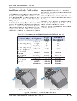
VSM152-401 (205mm)
Low-Medium
SIG CW
3 o’clock
Low-High
N/A
N/A
Medium-High
N/A
N/A
VSM501-701 (240mm)
Low-Medium
SIG CW
3 o’clock
VSS751-901 (280mm)
VSS1051-1301
(310mm)
Low-High
SIG CCW
12 o’clock
VSS1551-2101
(350mm)
Medium-High
SIG CCW
12 o’clock
VSS2401-3001
(401mm)
Low-Medium
Incomplete
Incomplete
Low-High
Incomplete
Incomplete
Medium-High
Incomplete
Incomplete
12 o’clock outlet port
3 o’clock outlet port
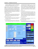
Figure 6-17. Port Inlet and Outlet Flow Directions
Table 6-1. Compressor Size and Liquid Injection Outlet Port Direction
Liquid Injection Outlet Port Direction
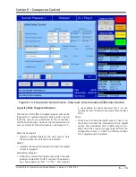
The toggle switch (S1) on the circuit board is used to se-
lect which port is the preferred “Pre Start-Up” outlet posi-
tion. The valve shall be at the lowest-pressure outlet posi-
tion at “Pre Start-Up” (i.e. low or medium, depending on
tubing positions).
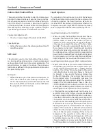
In the “SIG CCW” position, the actuator moves CCW
when the signal is energized during operation (based on
the switch pressure), until it reaches the limit - this makes
the 3 o’clock port the outlet port (Figure 6-17, right im-
age). Conversely, the other switch position, “SIG CW,”
makes the 12 o’clock port the outlet when the signal is
energized during operation (Figure 6-17, left image).
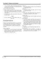
Each rotor diameter has a different port configuration on
the compressor housing.
For 205mm: there are only medium and low-ratio ports,
both of which are located on both top and bottom of the
housing.
For 240mm-350mm: low ports are located on the top
and bottom of the compressor, the medium port is on
the top, and the high port is on the bottom.
For 401mm: all three ports are located on both the top
and bottom of the housing.
Summary of Contents for Vilter Vission 20/20
Page 1: ...Vission 20 20TM Micro controller Operation and service manual Version 2 7 ...
Page 2: ......
Page 4: ......
Page 220: ...B 2 Blank Vission 20 20 Operation and Service Manual Emerson 35391SC 2 7 ...
Page 300: ...D 2 Blank Vission 20 20 Operation and Service Manual Emerson 35391SC 2 6 ...
Page 336: ......
Page 337: ......

