B - 47
Appendix B
•
Vission 20/20 Application Procedures
Vission 20/20 • Operation and Service Manual • Emerson • 35391SC 2.7
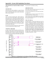
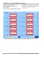
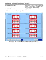
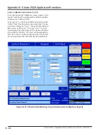
Figure B-36. Vibration Monitoring - Step 2 (Analog Auxiliary Screen, Page 4)
Step 2: Configure Analog Auxiliary Inputs
From the Configuration screen, page 4, select the num
-
ber of Analog Auxiliary Inputs. In this case, since the
Vibration Transmitter outputs two signals, a 4-20 mA
Fault Detector signal and a 4-20 mA Overall Vibration
signal, two auxiliary inputs are needed, Input #1 and
Input #2.
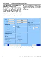
In the Set Name field, add a description for each auxil
-
iary input. In this case, Input #1 is “overall vibration” and
Input #2 is “Fault Detector”. Adding in the names here
will now allow other associated name fields to be popu
-
lated as shown in Step 3.
Summary of Contents for Vilter Vission 20/20
Page 1: ...Vission 20 20TM Micro controller Operation and service manual Version 2 7 ...
Page 2: ......
Page 4: ......
Page 220: ...B 2 Blank Vission 20 20 Operation and Service Manual Emerson 35391SC 2 7 ...
Page 300: ...D 2 Blank Vission 20 20 Operation and Service Manual Emerson 35391SC 2 6 ...
Page 336: ......
Page 337: ......

