B - 48
Appendix B
•
Vission 20/20 Application Procedures
Vission 20/20 • Operation and Service Manual • Emerson • 35391SC 2.7
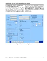
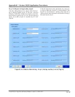
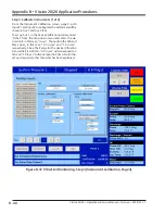
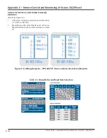
Figure B-37. Vibration Monitoring - Step 3 (Instrument Calibration, Page 4)
Step 3: Calibrate Instruments (1 of 2)
From the Instrument Calibration screen, page 4, with
Input #1 and Input #2 configured, the Set Names will be
shown in Aux 1 and Aux 2 tabs.
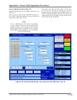
To set up Aux 1, in the Device Calibration window, select
“Other” from the drop-down menu and enter the de-
sired unit, in this case, “in,sec”. Then add in the Min and
Max values, in this case, “0.0 in,sec” and “1.0 in,sec”,
respectively. Since the Range for the device (Vibration
Transmitter) is 4-20 mA, “0.0 in,sec” will correspond to 4
mA and “1.0 in,sec” will correspond to 20 mA. No further
set up is required, other than what has been explained.
Summary of Contents for Vilter Vission 20/20
Page 1: ...Vission 20 20TM Micro controller Operation and service manual Version 2 7 ...
Page 2: ......
Page 4: ......
Page 220: ...B 2 Blank Vission 20 20 Operation and Service Manual Emerson 35391SC 2 7 ...
Page 300: ...D 2 Blank Vission 20 20 Operation and Service Manual Emerson 35391SC 2 6 ...
Page 336: ......
Page 337: ......


