B - 29
Appendix B
•
Vission 20/20 Application Procedures
Vission 20/20 • Operation and Service Manual • Emerson • 35391SC 2.7
Step 5: Auxiliary I/O (Analog Inputs) Alarm and
Trip Setup
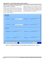
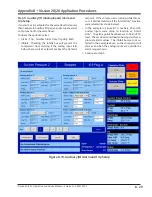
If an alarm or trip setpoint for the vessel level is desired,
then navigate to Auxiliary I/O page 3 and setup any alarm
or trip function for the vessel level.
You have the option to select:
• Alarm / Trip : Neither, Alarm Only, Trip Only, Both
• Inhibit: Checking the Inhibit box will prevent the
compressor from starting if the analog input falls
below the Low Alarm setpoint or above the Hi Alarm
setpoint. If the compressor is running while this oc-
curs, it will not shutdown if the “Alarm Only” function
were selected (as shown below).
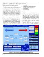
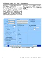
• In the example in Figure B-19, Auxiliary #5 and #6
Analog Inputs were setup to function as “Alarm
Only”. The alarm points have been set to 0% and 75%
level. These values would need to be adjusted for ap-
propriate alarm values. The inhibit box was not se-
lected in the example above, so the compressor will
start even when the analog inputs are outside the
alarm ranges shown.
• Continue to step 6.
Figure B-19. Auxiliary I/O Alarm and Trip Setup
Summary of Contents for Vilter Vission 20/20
Page 1: ...Vission 20 20TM Micro controller Operation and service manual Version 2 7 ...
Page 2: ......
Page 4: ......
Page 220: ...B 2 Blank Vission 20 20 Operation and Service Manual Emerson 35391SC 2 7 ...
Page 300: ...D 2 Blank Vission 20 20 Operation and Service Manual Emerson 35391SC 2 6 ...
Page 336: ......
Page 337: ......


