B - 26
Appendix B
•
Vission 20/20 Application Procedures
Vission 20/20 • Operation and Service Manual • Emerson • 35391SC 2.7
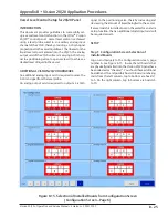
Step 2: Selection and Naming of Auxiliary Analog
Outputs used for Level Control
Navigate to page 7 of the Configuration screen and se
-
lect the analog output(s) that will be used modulating
the positioning valve(s) on the vessel(s). Also provide
a name for the analog output(s). You’ll need to refer-
ence your wiring diagram to determine which analog
output(s) need to be enabled.
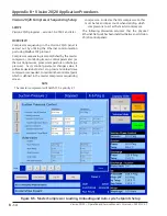
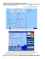
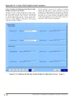
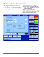
In the example in Figure B-16, Auxiliary #1 Analog
Output was renamed to “Chiller Level 4,20 Out” and
Auxiliary #2 Analog Output was renamed to “Condenser
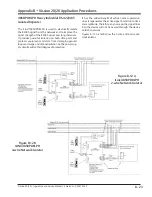
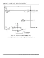
Level 4,20 Out”. Referencing the wiring diagram, please
note that Aux #1 Analog Output corresponds to AO#5
on the wiring diagram, and Aux #2 Analog Output cor-
responds to AO#6 of the wiring diagram.
Figure B-16. Enabling and Naming Analog Outputs (Configuration Screen – Page 7)
Summary of Contents for Vilter Vission 20/20
Page 1: ...Vission 20 20TM Micro controller Operation and service manual Version 2 7 ...
Page 2: ......
Page 4: ......
Page 220: ...B 2 Blank Vission 20 20 Operation and Service Manual Emerson 35391SC 2 7 ...
Page 300: ...D 2 Blank Vission 20 20 Operation and Service Manual Emerson 35391SC 2 6 ...
Page 336: ......
Page 337: ......

