D - 33
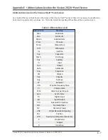
Appendix D
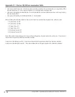
•
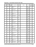
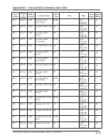
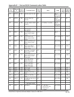
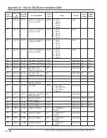
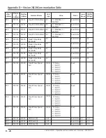
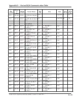
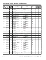
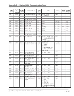
Vission 20/20 Communication Table
Vission 20/20 • Operation and Service Manual • Emerson • 35391SC 2.7
NOTES
•
Analog Outputs: spare1 / spare2 / spare3 – send a floating point value between 4.0 and 20.0 to drive a 4-20 mA
signal output (assumes proper calibration)
• Statuses: Alarm Status Word(s) – currently 20 alarms, so both Alarm Status Word 1 and 2 are used, with each posi-
tion indicating an alarm:
Word 1
Word 2
Bit 0 = Low Oil Pressure Alarm
Bit 0 = High Oil Separator Temp. Alarm
Bit 1 = Add Oil to the middle sight glass
Bit 1 = Low Suction Superheat Temp Alarm
Bit 2 = Low Oil Injection Temp. Alarm
Bit 2 = Low Process Pressure Alarm
Bit 3 = High Filter Differential Alarm
Bit 3 = High Process Pressure Alarm
Bit 4 = Low Suction Temp. Alarm
Bit 4 = Unused
Bit 5 = High Discharge Temp. Alarm
Bit 5 = Unused
Bit 6 = Low Suction Pressure Alarm
Bit 6 = Unused
Bit 7 = High Discharge Pressure Alarm
Bit 7 = Unused
Bit 8 = High Process Temp. Alarm
Bit 8 = Unused
Bit 9 = Low Process Temp. Alarm
Bit 9 = Unused
Bit 10 = Low Oil Separator Temp. Alarm
Bit 10 = Unused
Bit 11 = High Oil Injection Temp. Alarm
Bit 11 = Unused
Bit 12 = High Motor Current Alarm
Bit 12 = Unused
Bit 13 = Remote Comm Time-out
Bit 13 = Unused
Bit 14 = High Superheat Run Temp. Alarm
Bit 14 = Unused
Bit 15 = Low Run Pressure Ratio Alarm
Bit 15 = Unused
MSB
LSB
[Bit 15, Bit 14, Bit 13, ... Bit 3, Bit 2, Bit 1, Bit 0]
Summary of Contents for Vilter Vission 20/20
Page 1: ...Vission 20 20TM Micro controller Operation and service manual Version 2 7 ...
Page 2: ......
Page 4: ......
Page 220: ...B 2 Blank Vission 20 20 Operation and Service Manual Emerson 35391SC 2 7 ...
Page 300: ...D 2 Blank Vission 20 20 Operation and Service Manual Emerson 35391SC 2 6 ...
Page 336: ......
Page 337: ......

