C - 26
Appendix C
•
Remote Control and Monitoring of Vission 20/20 Panel
Vission 20/20 • Operation and Service Manual • Emerson • 35391SC 2.7
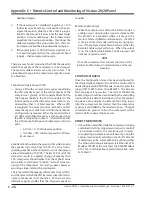
Typically, the following registers are setup (written to)
before a “Start” command is issued to the compressor:
Modbus Register 40502 - Remote Capacity
Control Selection
•
0 = Auto Capacity Control. This selection defines that
the 20/20 will control compressor capacity from its
internal Control Setpoints.
•
1 = Pulse Load/Unload. This selection defines that
the 20/20 will control compressor capacity from con-
tents of Pulse Load register 40504 and Pulse Unload
register 40505.
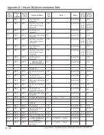
• For correlation between register content and
pulse value, see Table D-1.
•
2 = Hold Capacity %. This selection defines that the
20/20 will control compressor capacity from con-
tents of Capacity Hold % register 40506.
If Hold Capacity % is selected, then it is typical to write a
Capacity Hold value to register 40506 before the com-
pressor is started, typically 5%, to prevent the compres-
sor from loading immediately.
Modbus Register 40506 - Capacity Hold %
Value = 0-100
Hold Capacity Operation
•
Capacity Hold commands define a “target” capacity
slide valve position for the compressor. The 20/20
will position the capacity slide to the “target” posi-
tion. rules of this capacity hold algorithm are;
1. If the new target is < 0.4% (full scale) away from the
current position – then don’t do anything – this is
the deadband region.
2. If new target is > deadband region but < 10% (full
scale) away from the current position, then en-
ergize the capacity slide for a time that is propor-
tional to the amount it is away from the new target
position. To say it another way – the further you are
away from the new target position – the longer the
slide is energized in the proper direction. This con-
trol region is called the proportional band region.
3. If new target is > 10% (full scale) away from current
position (greater than the proportional band re-
gion) – then energize continuously.
There are mechanical properties that limit the speed at
which the capacity of the compressor can be changed.
The capacity slide actuators can only turn so fast. The
proportional change to the compressor capacity occurs
at a fixed rate.
Caphold and Operation with VFD
• Using a VFD with a compressor requires considering
the VFD capacity as part of the entire capacity of the
compressor. Typically, a VFD is operated from 50% to
100% speed, therefore the VFD is considered ½ the
total capacity and the slide valve movement is con-
sidered the other ½ of total capacity. When a VFD
is employed, the normal control method is to first
move the capacity slide from 0-100% when addition-
al refrigeration is required. When the capacity slide is
at 100% and additional capacity is still required, then
the VFD is ramped up in speed. It follows then that a
Caphold value of 25% will move the capacity slide to
50% position. A Caphold value of 50% will move the
capacity slide to 100% position. A Caphold value of
75% will move the capacity slide to 100% and the VFD
to 50% speed... and so on.
Consideration should also be given so that when moving
the capacity slide valve from 0-100%, the actual corre-
sponding capacity of the compressor is not changing in
a linear relationship of 0-100%. The last 15% travel of the
slide valve results in a greater change of capacity than
15%. Integrators should realize that the caphold value
sent relates to slide valve “position” and not actual ca-
pacity of the compressor. For most purposes however,
assuming a linear relationship is adequate.
The rate at which the capacity slide moves from 0-100%,
and the rate at which the VFD increases speed from min-
imum to maximum is not the same. So there are two
different capacity profiles that the integrator needs to
consider.
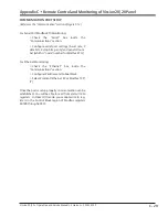
Modbus Register 40507 - Active Setpoint.
This register is used in conjunction with Register 40502
= 0, Auto Capacity Control mode.
1 = Setpoint #1 Active
2 = Setpoint #2 Active (note: you must enable two
setpoints from configuration screen first).
Sometimes compressors are switched from Suction
Pressure control mode to Process Temp control mode or
vice versa. This can be done via communications using
the following register.
Summary of Contents for Vilter Vission 20/20
Page 1: ...Vission 20 20TM Micro controller Operation and service manual Version 2 7 ...
Page 2: ......
Page 4: ......
Page 220: ...B 2 Blank Vission 20 20 Operation and Service Manual Emerson 35391SC 2 7 ...
Page 300: ...D 2 Blank Vission 20 20 Operation and Service Manual Emerson 35391SC 2 6 ...
Page 336: ......
Page 337: ......

