B - 35
Appendix B
•
Vission 20/20 Application Procedures
Vission 20/20 • Operation and Service Manual • Emerson • 35391SC 2.7
87
88
CR
N
V-PLUS Motor Start
(CR installed by others)
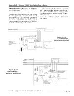
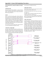
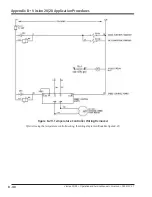
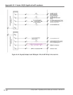
Figure B-24. Digital Output Card Wiring to VPLUS Liquid Injection Solenoid and VPLUS VFD Start
**
Liquid Injection #1 Solenoid is energized and de-energized via the “Liquid
Injection Setpoint #1” setpoint in the Control Limits Menu (Liquid
Injection Section). The Oil Separator Temp Override Setpoint is also
active and will not allow the Liquid Injection solenoid to energize
until the Oil Separator Temp is above the Oil Separator Temp Override
Setpoint.
**
*
The Control Relay (CR) can be installed in the V-PLUS panel or Vission 20/20
panel. Connections 87 and 88 are in the V-PLUS panel, see Figure
B-23.
*
Summary of Contents for Vilter Vission 20/20
Page 1: ...Vission 20 20TM Micro controller Operation and service manual Version 2 7 ...
Page 2: ......
Page 4: ......
Page 220: ...B 2 Blank Vission 20 20 Operation and Service Manual Emerson 35391SC 2 7 ...
Page 300: ...D 2 Blank Vission 20 20 Operation and Service Manual Emerson 35391SC 2 6 ...
Page 336: ......
Page 337: ......


