CPLD and FPGA
ATCA-8310 Installation and Use (6806800M72D)
351
6
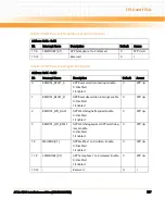
SPI Busy Bit:
0: Ready for next read or write access
1: Busy. The SPI clock is still toggling.
0
SPP: r
7
Enable GPP Boot SPI Flash Program Interface
0: Program Interface disabled. Bit 0 is always 1. Write to GPP Boot
SPI Flash Data Register is ignored and read deliver 0.
Only GPP has access to the GPP Boot SPI flashes
1: Program Interface enabled. Chip Select is controlled by Bit 0 and
read and write accesses to GPP Boot SPI Flash Data Register are
accepted.
SPP has access to the GPP Boot SPI flashes.
Note: The write value is synchronized with falling edge of GPP
platform reset PLTRST_.
When this bit is set 1 to enable the Program interface this register
must be polled and only when this bit is read 1 the SPP has the
ownership of the interface. When the bit is 1 the SPP can access one
the GPP SPI flashes.
When this bit is set 0 this register must be polled until the bit is read
0. When the bit is low the GPP is owner of GPP Boot SPI Flash
interface.
0
SPP: r/w
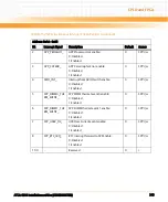
Table 8-169 GPP Boot SPI Flash Data Register
Address: 0xD3
Bit Description
Default
Access
7:0
GPP Boot SPI Flash Write Data Register.
A write triggers 8 SPI clocks and shifts the data out to MOSI. The
Data on MISO is shifted in.
-
SPP: w
GPP Boot SPI Flash Data Register.
Contains the data shifted in by the last write access to GPP Boot SPI
Flash Data Register
0
SPP: r
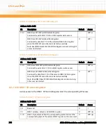
Table 8-168 GPP Boot SPI Flash Control Register (continued)
Address: 0xD2
Bit Description
Default
Access
Summary of Contents for ATCA-8310
Page 12: ...ATCA 8310 Installation and Use 6806800M72D Contents 12 Contents Contents ...
Page 26: ...ATCA 8310 Installation and Use 6806800M72D 26 List of Figures ...
Page 34: ...ATCA 8310 Installation and Use 6806800M72D About this Manual 34 About this Manual ...
Page 54: ...Hardware Preparation and Installation ATCA 8310 Installation and Use 6806800M72D 54 ...
Page 70: ...Controls Indicators and Connectors ATCA 8310 Installation and Use 6806800M72D 70 ...
Page 162: ...BIOS ATCA 8310 Installation and Use 6806800M72D 162 ...
Page 200: ...U Boot ATCA 8310 Installation and Use 6806800M72D 200 ...
Page 244: ...Intelligent Peripheral Management Controller ATCA 8310 Installation and Use 6806800M72D 244 ...
Page 438: ...CPLD and FPGA ATCA 8310 Installation and Use 6806800M72D 438 ...
Page 442: ...Replacing the Battery ATCA 8310 Installation and Use 6806800M72D 442 ...
Page 444: ...Related Documentation ATCA 8310 Installation and Use 6806800M72D 444 ...
Page 454: ...ATCA 8310 Installation and Use 6806800M72D Sicherheitshinweise 454 ...
Page 456: ...Index ATCA 8310 Installation and Use 6806800M72D 456 ...
Page 457: ...Index ATCA 8310 Installation and Use 6806800M72D 457 ...
Page 458: ...Index ATCA 8310 Installation and Use 6806800M72D 458 ...
Page 459: ......

