


U-Boot
ATCA-8310 Installation and Use (6806800M72D)
191
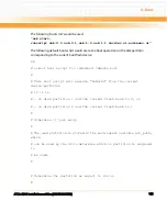
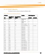
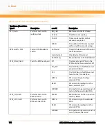
setenv hwconfig "fsl_ddr:ctlr_intlv=bank"
z
Superbank interleaving
setenv hwconfig "fsl_ddr:ctlr_intlv=superbank"
z
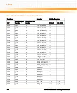
"Disable bank (chip-select) interleaving
setenv hwconfig "fsl_ddr:bank_intlv=null"
z
Bank (chip-select) interleaving cs0+cs1
setenv hwconfig "fsl_ddr:bank_intlv=cs0_cs1"
z
Bank (chip-select) interleaving cs2+cs3
setenv hwconfig "fsl_ddr:bank_intlv=cs2_cs3"
z
"Bank (chip-select) interleaving (cs0+cs1) and (cs2+cs3) (2x2)
setenv hwconfig "fsl_ddr:bank_intlv=cs0_cs1_and_cs2_cs3"
z
Bank (chip-select) interleaving (cs0+cs1+cs2+cs3) (4x1)
setenv hwconfig "fsl_ddr:bank_intlv=cs0_cs1_cs2_cs3"
Use the "saveenv" command to apply the changes.
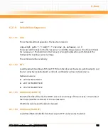
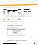
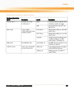
6.2.1.12 SRIO Initialization
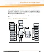
U-boot sets up the two SRIO interfaces connected to the TSI572 SRIO switch as well as the
TSI572 device itself.
The SRIO switch has two connections to the P4080, and two connections for each of the three
DSP blocks. All DSPs in each DSP block are connected in a daisy chain, with the first and the last
DSP in each chain connected to the SRIO switch.
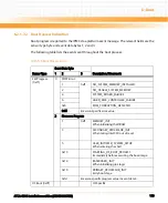
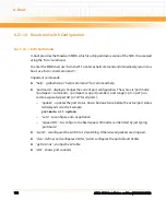
The port and SRIO target ID assignment are shown in the following table:
Table 6-9 Port and SRIO Target ID Assignment
Device
Target ID(s)
TSI572 Port(s)
P4080/SRIO1
0
1
P4080/SRIO2
0x40
0
Onboard DSPs
0x10 .. 0x19
6 (start of chain)
7 (end of chain)
DMC1 DSPs
0x20 .. 0x29
2 (start of chain)
3 (end of chain)
Summary of Contents for ATCA-8310
Page 12: ...ATCA 8310 Installation and Use 6806800M72D Contents 12 Contents Contents ...
Page 26: ...ATCA 8310 Installation and Use 6806800M72D 26 List of Figures ...
Page 34: ...ATCA 8310 Installation and Use 6806800M72D About this Manual 34 About this Manual ...
Page 54: ...Hardware Preparation and Installation ATCA 8310 Installation and Use 6806800M72D 54 ...
Page 70: ...Controls Indicators and Connectors ATCA 8310 Installation and Use 6806800M72D 70 ...
Page 162: ...BIOS ATCA 8310 Installation and Use 6806800M72D 162 ...
Page 200: ...U Boot ATCA 8310 Installation and Use 6806800M72D 200 ...
Page 244: ...Intelligent Peripheral Management Controller ATCA 8310 Installation and Use 6806800M72D 244 ...
Page 438: ...CPLD and FPGA ATCA 8310 Installation and Use 6806800M72D 438 ...
Page 442: ...Replacing the Battery ATCA 8310 Installation and Use 6806800M72D 442 ...
Page 444: ...Related Documentation ATCA 8310 Installation and Use 6806800M72D 444 ...
Page 454: ...ATCA 8310 Installation and Use 6806800M72D Sicherheitshinweise 454 ...
Page 456: ...Index ATCA 8310 Installation and Use 6806800M72D 456 ...
Page 457: ...Index ATCA 8310 Installation and Use 6806800M72D 457 ...
Page 458: ...Index ATCA 8310 Installation and Use 6806800M72D 458 ...
Page 459: ......


