


CPLD and FPGA
ATCA-8310 Installation and Use (6806800M72D
)
282
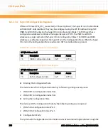
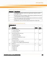
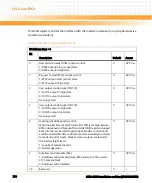
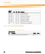
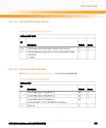
In the Line Control Register (LCR), the system programmer specifies the format of the
asynchronous data communications exchange. The serial data format consists of a start bit
(logic 0), five to eight data bits, an optional parity bit, and one or two stop bits (logic 1). The
LCR has bits for accessing the Divisor Latch and causing a break condition. The programmer
can also read the contents of the Line Control Register. The read capability simplifies system
programming and eliminates the need for separate storage in system memory.
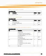
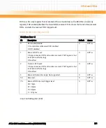
Table 8-57 Line Control Register (LCR)
IO Address: Base + 3
Bit
Description
Default
Access
1:0
Serial character WORD length:
00: 5 bits
01: 6 bits
10: 7 bits
11: 8 bits
0
GPP: r/w
2
Stop bit length:
1: 1.5 stop bits for 5 bit WORD length
1: 2 stop bits for 6, 7, and 8 bit WORD length
0: 1 stop bit for any serial character WORD length
0
GPP: r/w
3
Parity enable/disable
When bit 3 is set, a parity bit is generated in transmitted data
between the last data WORD bit and the first stop bit. In received
data, if bit 3 is set, parity is checked. When bit 3 is cleared, no parity
is generated or checked.:
1: Parity enabled
0: Parity disabled
0
GPP: r/w
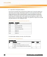
4
Parity even/odd
When parity is enabled and bit 4 is set, even parity (an even
number of logic ones in the data and parity bits) is selected. When
parity is disabled and bit 4 is cleared, odd parity (an odd number of
logic ones) is selected.:
1: Even parity
0: Odd parity
0
GPP: r/w
Summary of Contents for ATCA-8310
Page 12: ...ATCA 8310 Installation and Use 6806800M72D Contents 12 Contents Contents ...
Page 26: ...ATCA 8310 Installation and Use 6806800M72D 26 List of Figures ...
Page 34: ...ATCA 8310 Installation and Use 6806800M72D About this Manual 34 About this Manual ...
Page 54: ...Hardware Preparation and Installation ATCA 8310 Installation and Use 6806800M72D 54 ...
Page 70: ...Controls Indicators and Connectors ATCA 8310 Installation and Use 6806800M72D 70 ...
Page 162: ...BIOS ATCA 8310 Installation and Use 6806800M72D 162 ...
Page 200: ...U Boot ATCA 8310 Installation and Use 6806800M72D 200 ...
Page 244: ...Intelligent Peripheral Management Controller ATCA 8310 Installation and Use 6806800M72D 244 ...
Page 438: ...CPLD and FPGA ATCA 8310 Installation and Use 6806800M72D 438 ...
Page 442: ...Replacing the Battery ATCA 8310 Installation and Use 6806800M72D 442 ...
Page 444: ...Related Documentation ATCA 8310 Installation and Use 6806800M72D 444 ...
Page 454: ...ATCA 8310 Installation and Use 6806800M72D Sicherheitshinweise 454 ...
Page 456: ...Index ATCA 8310 Installation and Use 6806800M72D 456 ...
Page 457: ...Index ATCA 8310 Installation and Use 6806800M72D 457 ...
Page 458: ...Index ATCA 8310 Installation and Use 6806800M72D 458 ...
Page 459: ......


