


CPLD and FPGA
ATCA-8310 Installation and Use (6806800M72D)
287
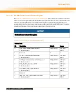
4
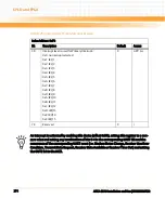
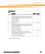
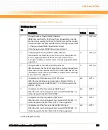
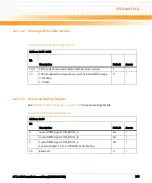
Break Interrupt (BI) indicator
When BI is set, it indicates that the received data input was held
low for longer than a full-word transmission time. A full-word
transmission time is defined as the total time to transmit the start,
data, parity, and stop bits. BI is cleared every time the CPU reads
the contents of the LSR. In the FIFO mode, this error is associated
with the particular character in the FIFO to which it applies. This
error is revealed to the CPU when its associated character is at the
top of the FIFO. When a break occurs, only one 0 character is
loaded into the FIFO. The next character transfer is enabled after
RXD goes to the marking state for at least two Receiver CLK
samples and then receives the next valid start bit:
1: Full WORD transmission time exceeded
0: Normal operation
0
GPP: r
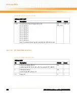
5
Transmit Holding Register Empty (THRE) indicator
THRE is set when the THR is empty, indicating that the ACE is ready
to accept a new character. If the THRE interrupt is enabled when
THRE is set, an interrupt is generated. THRE is set when the
contents of the THR are transferred to the TSR. THRE is cleared
concurrent with the loading of the THR by the CPU. In the FIFO
mode, THRE is set when the transmit FIFO is empty; it is cleared
when at least one byte is written to the transmit FIFO:
1: THR/Transmit FIFO empty
0: THR/Transmit FIFO contains data
1
GPP: r
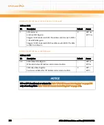
6
Transmitter Empty (TEMT) indicator
TEMT bit is set when the THR and the TSR are both empty. When
either the THR or the TSR contains a data character, TEMT is
cleared. In the FIFO mode, TEMT is set when the transmitter FIFO
and shift register are both empty:
1: THR/Transmit FIFO/TSR empty
0: THR/Transmit FIFO/TSR contains data
1
GPP: r
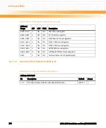
Table 8-59 Line Status Register (LSR) (continued)
IO Address: Base + 5
Bit Description
Default
Access
Summary of Contents for ATCA-8310
Page 12: ...ATCA 8310 Installation and Use 6806800M72D Contents 12 Contents Contents ...
Page 26: ...ATCA 8310 Installation and Use 6806800M72D 26 List of Figures ...
Page 34: ...ATCA 8310 Installation and Use 6806800M72D About this Manual 34 About this Manual ...
Page 54: ...Hardware Preparation and Installation ATCA 8310 Installation and Use 6806800M72D 54 ...
Page 70: ...Controls Indicators and Connectors ATCA 8310 Installation and Use 6806800M72D 70 ...
Page 162: ...BIOS ATCA 8310 Installation and Use 6806800M72D 162 ...
Page 200: ...U Boot ATCA 8310 Installation and Use 6806800M72D 200 ...
Page 244: ...Intelligent Peripheral Management Controller ATCA 8310 Installation and Use 6806800M72D 244 ...
Page 438: ...CPLD and FPGA ATCA 8310 Installation and Use 6806800M72D 438 ...
Page 442: ...Replacing the Battery ATCA 8310 Installation and Use 6806800M72D 442 ...
Page 444: ...Related Documentation ATCA 8310 Installation and Use 6806800M72D 444 ...
Page 454: ...ATCA 8310 Installation and Use 6806800M72D Sicherheitshinweise 454 ...
Page 456: ...Index ATCA 8310 Installation and Use 6806800M72D 456 ...
Page 457: ...Index ATCA 8310 Installation and Use 6806800M72D 457 ...
Page 458: ...Index ATCA 8310 Installation and Use 6806800M72D 458 ...
Page 459: ......


