U-Boot
ATCA-8310 Installation and Use (6806800M72D
)
190
6.2.1.11 Memory Initialization
6.2.1.11.1 Persistent Memory
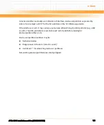
The Freescale P4080 provides a mechanism to configure the DDR3 devices into self-refresh
mode before an actual reset is performed. This feature is initiated by the glue logic FPGA, but
also requires configuring a P4080 external interrupt pin (interrupt 5) as "panic interrupt".
U-boot configures everything as required, but if the operating system re-configures the
interrupt controller it might disable the mechanism. To re-enable it, the following register
writes are necessary:
z
Set register at address 0xfe0500a0 (EIVPR5 register) to 0x004f0000
z
Set register at address 0xfe0500b8 (EILR5 register) to 0x000000f0
U-boot will not re-write the memory contents when it comes out of a reset (except power-up
reset). Instead, it will re-read the whole memory and check for ECC errors. Only for the case
that an ECC error is detected the memory is rewritten.
Refer to a description of the u-boot variables "pram", "pmem_disable" and "clear_mem_top" for
further options related to persistent memory.
6.2.1.11.2 Memory Interleaving
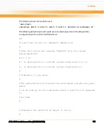
By default, U-boot disables memory interleaving. Depending on the application, it might be
desired to enable specific interleaving options for maximum performance.
The U-boot variable "hwconf" can be set to enable interleaving. Note that only two chip selects
(cs0 and cs1) are used on the ATCA-8310.
z
Disable memory controller interleaving:
setenv hwconfig "fsl_ddr:ctlr_intlv=null"
or
setenv hwconfig
z
Cacheline interleaving:
setenv hwconfig "fsl_ddr:ctlr_intlv=cacheline"
z
Page interleaving:
setenv hwconfig "fsl_ddr:ctlr_intlv=page"
z
Bank interleaving
Summary of Contents for ATCA-8310
Page 12: ...ATCA 8310 Installation and Use 6806800M72D Contents 12 Contents Contents ...
Page 26: ...ATCA 8310 Installation and Use 6806800M72D 26 List of Figures ...
Page 34: ...ATCA 8310 Installation and Use 6806800M72D About this Manual 34 About this Manual ...
Page 54: ...Hardware Preparation and Installation ATCA 8310 Installation and Use 6806800M72D 54 ...
Page 70: ...Controls Indicators and Connectors ATCA 8310 Installation and Use 6806800M72D 70 ...
Page 162: ...BIOS ATCA 8310 Installation and Use 6806800M72D 162 ...
Page 200: ...U Boot ATCA 8310 Installation and Use 6806800M72D 200 ...
Page 244: ...Intelligent Peripheral Management Controller ATCA 8310 Installation and Use 6806800M72D 244 ...
Page 438: ...CPLD and FPGA ATCA 8310 Installation and Use 6806800M72D 438 ...
Page 442: ...Replacing the Battery ATCA 8310 Installation and Use 6806800M72D 442 ...
Page 444: ...Related Documentation ATCA 8310 Installation and Use 6806800M72D 444 ...
Page 454: ...ATCA 8310 Installation and Use 6806800M72D Sicherheitshinweise 454 ...
Page 456: ...Index ATCA 8310 Installation and Use 6806800M72D 456 ...
Page 457: ...Index ATCA 8310 Installation and Use 6806800M72D 457 ...
Page 458: ...Index ATCA 8310 Installation and Use 6806800M72D 458 ...
Page 459: ......

