


CPLD and FPGA
ATCA-8310 Installation and Use (6806800M72D
)
436
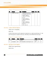
and receive state machines are located in different FPGA's, which do not start up synchronously
in general, a resynchronization trigger (SerDesTrmCtrlReg: SerdesTrmResync) may be
necessary. If the transmission link is established the SerDesRcvStatReg:
SerdesRcvHasFoundComma bit is set.
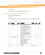
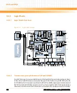
8.4.3.4
Pseudo Random Generator and Comparator (PRGC)
The DSP FPGA contains a pseudo random generator and the related comparator according to
ITU-T O.150. The generator can be linked to any TSIP link and any channel depending on the
configuration register. The comparator fetches the configured TSIP channel and compares it to
the transmitted pattern if the generator is switched on. Errors are counted and the error rate is
provided to the internal wishbone interface. Injection of pseudo random pattern or static
pattern is possible.
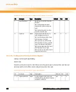
8.4.3.5
DSP Status and Interrupt Interface (DSI)
The DSI collects the following status information inputs from the DSP module:
z
RESETSTAT_N(0..9) (Input), status is low when DSP is in Reset
z
BOOTACTIVE_N(0..9) (Input), status is low when DSP boot is active
z
DSP_HOUT(0..9) (Input), host event output from DSPs
z
DSP_WDOUT(0..9) (Input), watchdog output from DSPs
The status information is buffered in the DSI register set accessible to the internal Wishbone
interface and if a status change occurs the host controller is informed via the interrupt outputs:
z
DMC_HOUT_DSP_N (Output), Host event
z
DMC_FAILURE_N (Ouput), Module failure indication
The interrupts are maskable.
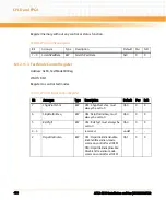
8.4.3.6
Base ID and Sub module ID Register (BSID)
The BSID has four BASE_ID (3..0) input pins and a read register accessible to internal Wishbone
interface.
8.4.3.7
Debug LEDs
The DSP FPGA drives a set of eight LEDs for status notification and debug purposes.
Summary of Contents for ATCA-8310
Page 12: ...ATCA 8310 Installation and Use 6806800M72D Contents 12 Contents Contents ...
Page 26: ...ATCA 8310 Installation and Use 6806800M72D 26 List of Figures ...
Page 34: ...ATCA 8310 Installation and Use 6806800M72D About this Manual 34 About this Manual ...
Page 54: ...Hardware Preparation and Installation ATCA 8310 Installation and Use 6806800M72D 54 ...
Page 70: ...Controls Indicators and Connectors ATCA 8310 Installation and Use 6806800M72D 70 ...
Page 162: ...BIOS ATCA 8310 Installation and Use 6806800M72D 162 ...
Page 200: ...U Boot ATCA 8310 Installation and Use 6806800M72D 200 ...
Page 244: ...Intelligent Peripheral Management Controller ATCA 8310 Installation and Use 6806800M72D 244 ...
Page 438: ...CPLD and FPGA ATCA 8310 Installation and Use 6806800M72D 438 ...
Page 442: ...Replacing the Battery ATCA 8310 Installation and Use 6806800M72D 442 ...
Page 444: ...Related Documentation ATCA 8310 Installation and Use 6806800M72D 444 ...
Page 454: ...ATCA 8310 Installation and Use 6806800M72D Sicherheitshinweise 454 ...
Page 456: ...Index ATCA 8310 Installation and Use 6806800M72D 456 ...
Page 457: ...Index ATCA 8310 Installation and Use 6806800M72D 457 ...
Page 458: ...Index ATCA 8310 Installation and Use 6806800M72D 458 ...
Page 459: ......


