


U-Boot
ATCA-8310 Installation and Use (6806800M72D)
167
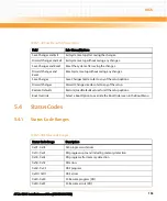
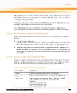
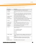
v_logical_slot
The logical slot number where the blade is mounted in.
v_bootbank
The physical boot bank number from which the blade has started (0
or 1).
v_shelf_id
The first byte of the shelf identifier as read from the shelf manager
v_location
Two bytes encoding the logical slot number and the 1st byte of the
shelf ID, each octet separated by a colon.
v_gl_fpga_version
The version of the onboard glue-logic FPGA.
v_dhcp_clid
The DHCP client ID (option 61) used in DHCP discover.
v_dhcp_clid_gpp
The GUID to be used by the GPP BIOS. This value is encoded in DHCP
option 97 when the GPP (PXE boot) sends a DHCP discover.
v_fman_uc
The hexadecimal memory address of the P4080 frame manager
micro-code.
v_uboot_version
The u-boot firmware version (in the format V<x>.<y>.<z>).
v_gpp_initstate
The state of the GPP at boot time. Values are "run" or "halt".
v_gpp_state
The last known state of the GPP. Values are "run" or "halt".
v_product_id
The name of the product: "ATCA-8310"
v_rtm_id
The name of the connected RTM (or "none" if no RTM is detected). The
different variants are:
z
none (no RTM assembled)
z
IP (no RTM mezzanine)
z
E1T1
z
DS3
z
OC3
v_failsafe_triggered
Set to 1 if the failsafe mechanism triggered an automatic boot bank
switch (i.e. failsafe was activated and the IPMI or FPGA watchdog
expired).
ethaddr
eth1addr
eth2addr
The Ethernet MAC addresses for the local network interfaces
(FM2@DTSEC0, FM2@DTSEC2 and FM1@TGEC0 respectively).
v_eeprom_ignored
The EEPROM contents have been ignored
Table 6-2 Dynamic Variables Set During the Boot Phase (continued)
Variable Name
Description
Summary of Contents for ATCA-8310
Page 12: ...ATCA 8310 Installation and Use 6806800M72D Contents 12 Contents Contents ...
Page 26: ...ATCA 8310 Installation and Use 6806800M72D 26 List of Figures ...
Page 34: ...ATCA 8310 Installation and Use 6806800M72D About this Manual 34 About this Manual ...
Page 54: ...Hardware Preparation and Installation ATCA 8310 Installation and Use 6806800M72D 54 ...
Page 70: ...Controls Indicators and Connectors ATCA 8310 Installation and Use 6806800M72D 70 ...
Page 162: ...BIOS ATCA 8310 Installation and Use 6806800M72D 162 ...
Page 200: ...U Boot ATCA 8310 Installation and Use 6806800M72D 200 ...
Page 244: ...Intelligent Peripheral Management Controller ATCA 8310 Installation and Use 6806800M72D 244 ...
Page 438: ...CPLD and FPGA ATCA 8310 Installation and Use 6806800M72D 438 ...
Page 442: ...Replacing the Battery ATCA 8310 Installation and Use 6806800M72D 442 ...
Page 444: ...Related Documentation ATCA 8310 Installation and Use 6806800M72D 444 ...
Page 454: ...ATCA 8310 Installation and Use 6806800M72D Sicherheitshinweise 454 ...
Page 456: ...Index ATCA 8310 Installation and Use 6806800M72D 456 ...
Page 457: ...Index ATCA 8310 Installation and Use 6806800M72D 457 ...
Page 458: ...Index ATCA 8310 Installation and Use 6806800M72D 458 ...
Page 459: ......


