CPLD and FPGA
ATCA-8310 Installation and Use (6806800M72D
)
354
8.2.3.3
Super IO Module
The Super IO consists of two serial devices COM1 and COM2 connected via the LPC bus
interface. The Super IO has the following features:
z
Serial IRQ interface compatible with serialized IRQ support for LPC systems
z
Two fully functional Serial ports COM1and COM2 compatible to 16550C
z
Configurable I/O addresses and interrupts
z
Configurable Pre-divider to support 48 MHz CLK_UART clock input
8.2.3.4
GPP Reset Controller
8.2.3.4.1 GPP XDP Debugger Reset
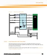
For debugging the XDP CPU debugger must be able to reset the board.
When PWR_GOOD is high and the reset signal GPP_XDP_DBR_ is asserted the reset signal
GPP_SYS_RST_ is driven low.
8.2.3.4.2 GPP Platform Reset
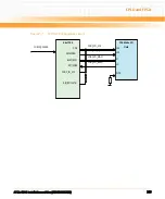
The GPP Platform Reset is asserted in the following cases:
z
Face Plate Push Button reset or ARMT Push Button reset.
z
SPP holds the GPP in reset
The GPP should stay in reset until reset source is released. A GPP reset is triggered by a falling
edge of GPP_SYS_RST_. GPP starts reboot even GPP_SYS_RST_ is still asserted. Therefore a
state machine is needed to keep the system in reset until the reset source is released.
The PCH signal GPP_SYS_RST_ is used to trigger a Cold Reset. The PCH has a 16 ms debounce
filter for the GPP_SYS_RST_ signal. Therefore the low and high states need to be stable for at
least 16 ms.
GPP_SYS_RST_ is edge sensitive. A high to low transition (after debounce time) triggers a cold
reset. The PCH asserts for 5 to 6 ms the platform reset signal GPP_PLTRST_. The reset may be
delayed depending on some system states.
Summary of Contents for ATCA-8310
Page 12: ...ATCA 8310 Installation and Use 6806800M72D Contents 12 Contents Contents ...
Page 26: ...ATCA 8310 Installation and Use 6806800M72D 26 List of Figures ...
Page 34: ...ATCA 8310 Installation and Use 6806800M72D About this Manual 34 About this Manual ...
Page 54: ...Hardware Preparation and Installation ATCA 8310 Installation and Use 6806800M72D 54 ...
Page 70: ...Controls Indicators and Connectors ATCA 8310 Installation and Use 6806800M72D 70 ...
Page 162: ...BIOS ATCA 8310 Installation and Use 6806800M72D 162 ...
Page 200: ...U Boot ATCA 8310 Installation and Use 6806800M72D 200 ...
Page 244: ...Intelligent Peripheral Management Controller ATCA 8310 Installation and Use 6806800M72D 244 ...
Page 438: ...CPLD and FPGA ATCA 8310 Installation and Use 6806800M72D 438 ...
Page 442: ...Replacing the Battery ATCA 8310 Installation and Use 6806800M72D 442 ...
Page 444: ...Related Documentation ATCA 8310 Installation and Use 6806800M72D 444 ...
Page 454: ...ATCA 8310 Installation and Use 6806800M72D Sicherheitshinweise 454 ...
Page 456: ...Index ATCA 8310 Installation and Use 6806800M72D 456 ...
Page 457: ...Index ATCA 8310 Installation and Use 6806800M72D 457 ...
Page 458: ...Index ATCA 8310 Installation and Use 6806800M72D 458 ...
Page 459: ......


