


BIOS
ATCA-8310 Installation and Use (6806800M72D
)
136
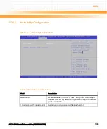
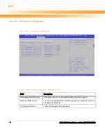
Parity
A parity bit can be sent with the data bits to detect some transmission
errors. Even: parity bit is 0 if the num of 1's in the data bits is even. Odd:
parity bit is 0 if num of 1's in the data bits is odd. Mark: parity bit is always
1. Space: Parity bit is always 0. Mark and Space Parity do not allow for
error detection. They can be used as an additional data bit.
Stop Bits
Stop bits indicate the end of a serial data packet. (A start bit indicates the
beginning). The standard setting is 1 stop bit. Communication with slow
devices may require more than 1 stop bit.
Flow Control
Flow control can prevent data loss from buffer overflow. When sending
data, if the receiving buffers are full, a 'stop' signal can be sent to stop the
data flow. Once the buffers are empty, a 'start' signal can be sent to re-
start the flow. Hardware flow control uses two wires to send start/stop
signals. Software flow control uses start/stop ASCII chars, which slows
down the data flow and can be problematic if binary data is being sent.
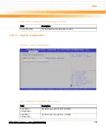
Recorder Mode
On this mode enabled only text will be send. This is to capture Terminal
data.
Resolution 100x31
Enables or disables extended terminal resolution
Legacy OS Redirection
On Legacy OS, the Number of Rows and Columns supported redirection
Table 5-24 Console Redirection Settings (continued)
Field
Description
Summary of Contents for ATCA-8310
Page 12: ...ATCA 8310 Installation and Use 6806800M72D Contents 12 Contents Contents ...
Page 26: ...ATCA 8310 Installation and Use 6806800M72D 26 List of Figures ...
Page 34: ...ATCA 8310 Installation and Use 6806800M72D About this Manual 34 About this Manual ...
Page 54: ...Hardware Preparation and Installation ATCA 8310 Installation and Use 6806800M72D 54 ...
Page 70: ...Controls Indicators and Connectors ATCA 8310 Installation and Use 6806800M72D 70 ...
Page 162: ...BIOS ATCA 8310 Installation and Use 6806800M72D 162 ...
Page 200: ...U Boot ATCA 8310 Installation and Use 6806800M72D 200 ...
Page 244: ...Intelligent Peripheral Management Controller ATCA 8310 Installation and Use 6806800M72D 244 ...
Page 438: ...CPLD and FPGA ATCA 8310 Installation and Use 6806800M72D 438 ...
Page 442: ...Replacing the Battery ATCA 8310 Installation and Use 6806800M72D 442 ...
Page 444: ...Related Documentation ATCA 8310 Installation and Use 6806800M72D 444 ...
Page 454: ...ATCA 8310 Installation and Use 6806800M72D Sicherheitshinweise 454 ...
Page 456: ...Index ATCA 8310 Installation and Use 6806800M72D 456 ...
Page 457: ...Index ATCA 8310 Installation and Use 6806800M72D 457 ...
Page 458: ...Index ATCA 8310 Installation and Use 6806800M72D 458 ...
Page 459: ......