


U-Boot
ATCA-8310 Installation and Use (6806800M72D)
165
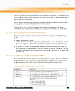
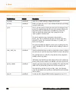
Although the "saveenv" command will store the complete set of variables currently being used
into the NVRAM, the actual setting of these variables might not become valid because they are
overridden by the other entities.
In particular, u-boot does not synchronize the NVRAM storage and the IPMI boot parameter
storage by itself. This is something the user has to be aware of.
If the NVRAM's CRC is invalid, the NVRAM is initialized with the blade's default values
immediately after detecting the bad CRC (before reading additional values from the IPMC).
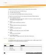
6.2.1.2.1 Passing Parameter Set to the Operating System
There are two ways how the current u-boot parameter set can be passed to the operating
system:
z
Via the firmware device tree
U-Boot generates a node "/u-boot-env", containing a node for each environment variable.
This is done by the "bootm" command as the final step before executing the OS image.
z
vxWorks: The "bootvx" command will initialize a vxWorks specific data structure at the
address encoded in the variable "vx_info_addr" (default is 0x4c00). The vxWorks BSP will
evaulate this structure and retrieve the u-boot environment data out of it (beneath other
information).
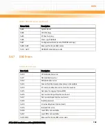
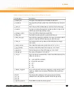
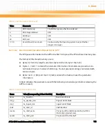
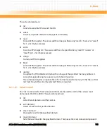
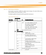
6.2.1.2.2 Dynamic Variables Set During the Boot Phase
This section lists the variables which are set during the boot phase. The general convention is
that these variables have a prefix "v_" to indicate that these variables are volatile, except for
some variables which are defined for compatibility with existing implementations.
Table 6-2 Dynamic Variables Set During the Boot Phase
Variable Name
Description
v_sol_ea
The Ethernet address assigned to the terminal server.
v_gpp_ea<n>
The three Ethernet MAC addresses assigned to the GPP (n=1..3).
v_dmc<n>_id
The assembly ID of the three DSP blocks, if present (n = 0 for the
onboard DSP block, n=1/2 for the two DMC modules.
Values are :
1 for an assembly with 2 DSPs
2 for an assembly with 5 DSPs
3 for an assembly with 10 DSPs
Summary of Contents for ATCA-8310
Page 12: ...ATCA 8310 Installation and Use 6806800M72D Contents 12 Contents Contents ...
Page 26: ...ATCA 8310 Installation and Use 6806800M72D 26 List of Figures ...
Page 34: ...ATCA 8310 Installation and Use 6806800M72D About this Manual 34 About this Manual ...
Page 54: ...Hardware Preparation and Installation ATCA 8310 Installation and Use 6806800M72D 54 ...
Page 70: ...Controls Indicators and Connectors ATCA 8310 Installation and Use 6806800M72D 70 ...
Page 162: ...BIOS ATCA 8310 Installation and Use 6806800M72D 162 ...
Page 200: ...U Boot ATCA 8310 Installation and Use 6806800M72D 200 ...
Page 244: ...Intelligent Peripheral Management Controller ATCA 8310 Installation and Use 6806800M72D 244 ...
Page 438: ...CPLD and FPGA ATCA 8310 Installation and Use 6806800M72D 438 ...
Page 442: ...Replacing the Battery ATCA 8310 Installation and Use 6806800M72D 442 ...
Page 444: ...Related Documentation ATCA 8310 Installation and Use 6806800M72D 444 ...
Page 454: ...ATCA 8310 Installation and Use 6806800M72D Sicherheitshinweise 454 ...
Page 456: ...Index ATCA 8310 Installation and Use 6806800M72D 456 ...
Page 457: ...Index ATCA 8310 Installation and Use 6806800M72D 457 ...
Page 458: ...Index ATCA 8310 Installation and Use 6806800M72D 458 ...
Page 459: ......


