www.eaton.com
IM02601004E
Page 69
5 Introduction to the Local Graphical Display
Turn to Highlight
BACK
Push to Select
Hold in for Help
Events
Health
Power Xpert
5 INTRODUCTION TO THE LOCAL GRAPHICAL DISPLAY
This chapter is an introduction to the Power Xpert Meter local display screens and describes how
to access basic information through them. Each option provides easy access to basic metering
functions as well as setup
configuration. Other information, such as
waveforms, trending graphs,
harmonic tables, phasors, and ITIC curves is also available.
Chapter 7, Functions on the Graphical Display Screens, provides more detailed information about
the functions, features and options available on each screen.
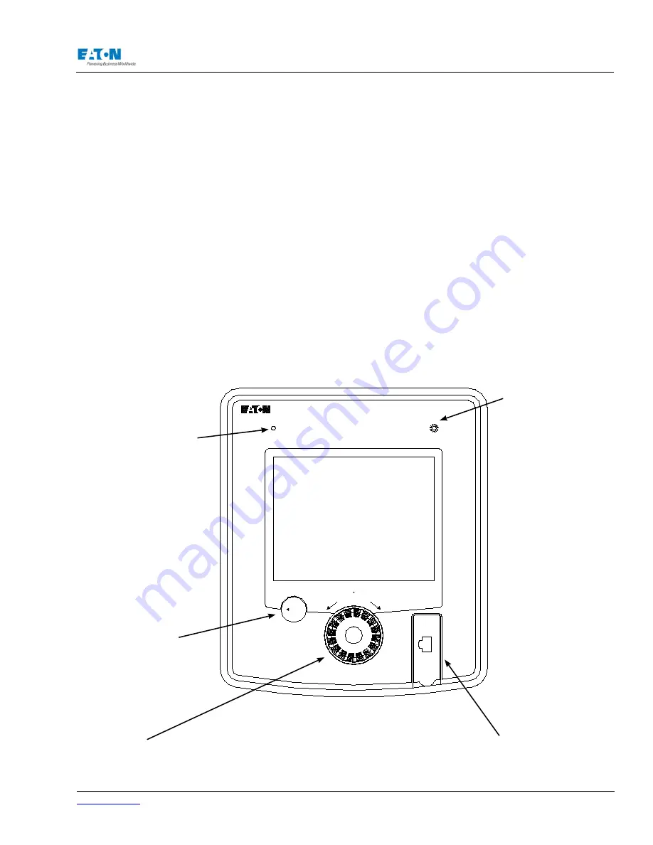
The Power Xpert Meter Graphical Display contains:
• Power Quality LED
• Events LED
• Back Button
• Navigator
• 10/100 Ethernet Port
Navigator
Turn to select (highlight) options on the screen. While high-
lighted, Push the Navigator to select the currently highlighted
function.
10/100 Ethernet
Port (for local
display network)
The Events LED
reflects the events status
for the meter to which
the display pointed, and
serves the same function
as the meter’s Status
LED.
The Events LED will
blink when there are
unacknowledged events
on the meter. Acknowl-
edging or or clearing the
events returns the LED
to an unlit state.
If the Events LED is in
a repeating pattern of
three blinks followed
by a long pause, then
the meter is in “factory
test mode.” Factory test
mode has DS 1 & 2 on
and the meter should
never be operated with
this setting. To correct
this, see the Trouble-
shooting chapter.
The Health LED
displays on/off status;
blinks slowly during
normal use as health
LED.
Back Button
Push in to return
to the previously
viewed screen.
Summary of Contents for Power Xpert PXM 4000
Page 1: ...User and Installation Manual IM02601004E Power Xpert PXM 4000 6000 8000 ...
Page 8: ...Page vi IM02601004E www eaton ...
Page 19: ...www eaton com IM02601004E Page 11 1 Introduction ...
Page 24: ...Page 16 IM02601004E www eaton ...
Page 36: ...Page 18 IM02601004E www eaton com 2 Quick Start Guide for the Meter Module ...
Page 45: ...www eaton com IM02601004E Page 37 3 Installation 3 8 MeterDimensions ...
Page 46: ...Page 38 IM02601004E www eaton 3 Installation Dimension Con t ...
Page 47: ...www eaton com IM02601004E Page 39 3 Installation Dimension Con t ...
Page 48: ...Page 40 IM02601004E www eaton 3 Installation Dimension Con t ...
Page 53: ...www eaton com IM02601004E Page 45 3 Installation ...
Page 54: ...Page 46 IM02601004E www eaton 3 Installation ...
Page 55: ...www eaton com IM02601004E Page 47 3 Installation ...
Page 56: ...Page 48 IM02601004E www eaton 3 Installation ...
Page 57: ...www eaton com IM02601004E Page 49 3 Installation ...
Page 58: ...Page 50 IM02601004E www eaton 3 Installation ...
Page 59: ...www eaton com IM02601004E Page 51 3 Installation ...
Page 60: ...Page 52 IM02601004E www eaton 3 Installation ...
Page 61: ...www eaton com IM02601004E Page 53 3 Installation ...
Page 62: ...Page 54 IM02601004E www eaton 3 Installation ...
Page 63: ...www eaton com IM02601004E Page 55 3 Installation ...
Page 66: ...Page 58 IM02601004E www eaton 3 Installation ...
Page 75: ...www eaton com IM02601004E Page 67 4 Introduction to Web Server Screens ...
Page 76: ...Page 68 IM02601004E www eaton 4 Introduction to Web Server Screens ...
Page 86: ...Page 78 IM02601004E www eaton 5 Introduction to the Local Graphical Display ...
Page 108: ...Page 100 IM02601004E www eaton 6 Functions on the Web Server Pages ...
Page 128: ...Page 120 IM02601004E www eaton 7 Functions on the Graphical Display ...
Page 164: ...Page 156 IM02601004E www eaton 8 Setup on the Web Server Pages ...
Page 198: ...Page 190 IM02601004E www eaton A MODBUS Communication ...
Page 242: ...Page 234 IM02601004E www eaton ...
Page 252: ...Page 244 IM02601004E www eaton D Diagnostics ...
Page 254: ...Page 246 IM02601004E www eaton D Diagnostics ...