www.eaton.com
IM02601004E
Page 125
8 Setup on the Web Server Pages
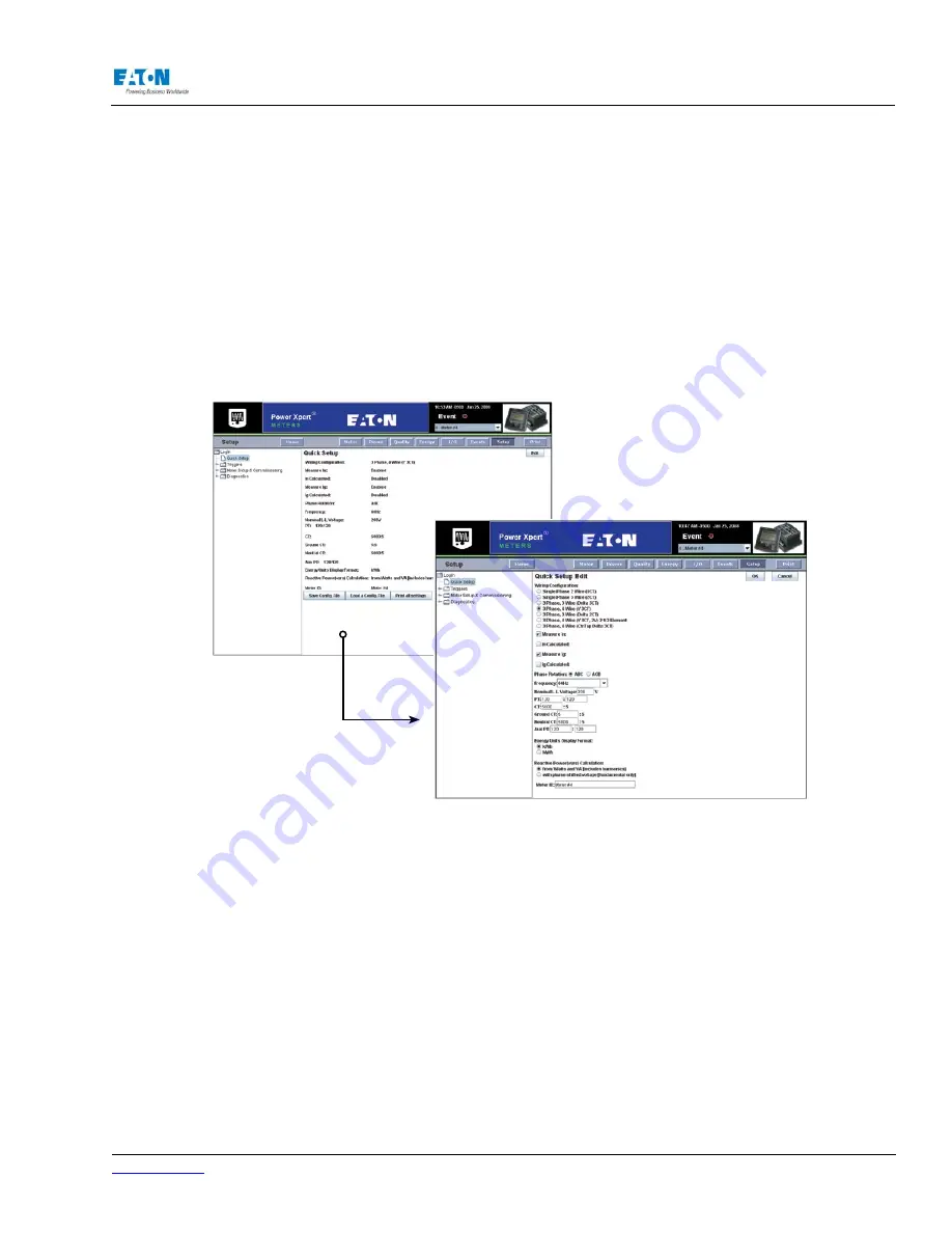
NOTE:
When both Measure In and Calculate In are selected, Measure In overrides the setting.
Enter the nominal line to line voltage. The Nominal line to line voltage value is used as a reference
for swells and sags monitoring.
Select the Phase Rotation based on the Phase Rotation of the Input Voltages. Select the Nominal
Frequency of the Input Voltages from the Frequency list.
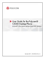
Locating Quick Setup On The Web
1. From the Setup Main Page, select Quick Setup from the tree structure. The page will update to
list all the current settings for Quick Setup. An Edit and an OK button will appear at the top of
the page.
2. Click Edit to change any of the listed settings.
3. Click OK when new entries are completed.
CONFIGURATION FILES
Configuration files can be downloaded to your local file system and then uploaded from your local
file system to a meter. This is a handy convenience feature, especially if you’re setting up multiple
meters with either the same or similar settings. You can set up one meter, download the configura
-
tion file to your local computer, and then upload that same configuration file to other meters. If you
want a hardcopy version of the meter settings, you can also create a formatted printout,
Note:
The configuration file is actually a ZIP file that contains multiple files, each with configuration
settings for a different aspect of the meter setup.
To download the current configuration file:
1.
Click Save Config. File.
2.
Give the file a name (the dialog will fill in the .zip) extension.
3. Click Save.
To upload a configuration file to a meter:
1.
Click Load a Config. File.
2.
Select a .zip file.
Summary of Contents for Power Xpert PXM 4000
Page 1: ...User and Installation Manual IM02601004E Power Xpert PXM 4000 6000 8000 ...
Page 8: ...Page vi IM02601004E www eaton ...
Page 19: ...www eaton com IM02601004E Page 11 1 Introduction ...
Page 24: ...Page 16 IM02601004E www eaton ...
Page 36: ...Page 18 IM02601004E www eaton com 2 Quick Start Guide for the Meter Module ...
Page 45: ...www eaton com IM02601004E Page 37 3 Installation 3 8 MeterDimensions ...
Page 46: ...Page 38 IM02601004E www eaton 3 Installation Dimension Con t ...
Page 47: ...www eaton com IM02601004E Page 39 3 Installation Dimension Con t ...
Page 48: ...Page 40 IM02601004E www eaton 3 Installation Dimension Con t ...
Page 53: ...www eaton com IM02601004E Page 45 3 Installation ...
Page 54: ...Page 46 IM02601004E www eaton 3 Installation ...
Page 55: ...www eaton com IM02601004E Page 47 3 Installation ...
Page 56: ...Page 48 IM02601004E www eaton 3 Installation ...
Page 57: ...www eaton com IM02601004E Page 49 3 Installation ...
Page 58: ...Page 50 IM02601004E www eaton 3 Installation ...
Page 59: ...www eaton com IM02601004E Page 51 3 Installation ...
Page 60: ...Page 52 IM02601004E www eaton 3 Installation ...
Page 61: ...www eaton com IM02601004E Page 53 3 Installation ...
Page 62: ...Page 54 IM02601004E www eaton 3 Installation ...
Page 63: ...www eaton com IM02601004E Page 55 3 Installation ...
Page 66: ...Page 58 IM02601004E www eaton 3 Installation ...
Page 75: ...www eaton com IM02601004E Page 67 4 Introduction to Web Server Screens ...
Page 76: ...Page 68 IM02601004E www eaton 4 Introduction to Web Server Screens ...
Page 86: ...Page 78 IM02601004E www eaton 5 Introduction to the Local Graphical Display ...
Page 108: ...Page 100 IM02601004E www eaton 6 Functions on the Web Server Pages ...
Page 128: ...Page 120 IM02601004E www eaton 7 Functions on the Graphical Display ...
Page 164: ...Page 156 IM02601004E www eaton 8 Setup on the Web Server Pages ...
Page 198: ...Page 190 IM02601004E www eaton A MODBUS Communication ...
Page 242: ...Page 234 IM02601004E www eaton ...
Page 252: ...Page 244 IM02601004E www eaton D Diagnostics ...
Page 254: ...Page 246 IM02601004E www eaton D Diagnostics ...