Page 76
IM02601004E
www.eaton.
5 Introduction to the Local Graphical Display
MeterNine
Meter
Power
Quality
Events
Setup
ITIC Curve
20 Events
Have occurred and not been addressed
Latest Event:
Wed, 28 Dec 2005 15:02:59 EST Transient Triggered
(View Events...) (Silence Buzzer...)
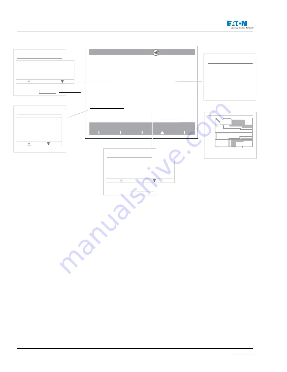
The Events main screen
11 Triggers
Are currently enabled
and not monitoring the System
(View Trigger Items...)
2,953 Log Items
...and old Events are be-
ing stored for historical
analysis
Silence Buzzer ???
(No screen comes up
when selected on Pow-
erXpert unit.)
Trigger List
Exit Trigger List
iTIC: L1 Sags
iTIC: L2 Sags
iTIC: L4 Sags
iTIC: L8 Sags
iTIC: L1 Swells
iTIC: L2 Swells
Fast Transient
Event List
Exit Event List
Wed, 28 Dec 2005 15:02:59 EST Transient Triggered
Wed, 26 Dec 2005 15:02:52 EST Transient Triggered
Wed, 26 Dec 2005 15:02:44 EST Transient Triggered
Wed, 26 Dec 2005 15:02:35 EST Transient Triggered
Wed, 26 Dec 2005 15:02:28 EST Transient Triggered
! = Event Still Active
x = Event Ack’d
Ack All Events (Reset All Events...)
Log List
Exit Log List
Wed, 25 Jan 2006 09:51:35 EST New Min (Fundamental Vbc
A)...
Wed, 25 Jan 2006 06:33:13 EST New Max (Even Harmonic In)...
Wed, 25 Jan 2006 06:33:13 EST New Max (Even Harmonic Ic)...
Wed, 25 Jan 2006 05:39:53 EST New Max (Fundamental In)=
Wed, 25 Jan 2006 05:39:53 EST New Max (Fundamental Ic)=0
(Reset All Logs...)
200
150
50
100
0
1
1 ms
10 sec
Voltage (% nominal)
Sag/Swell Duration
15 Tran-
sient
Pass 3
Fail 5
The meter can be setup to monitor events, such as low frequency, out of limit voltage, etc., by set-
ting up triggers. When activated, these triggers can sound a buzzer or send an e-mail.
From the Events main screen, detailed information about selected events in the Events List can be
reviewed. The Events List displays the time of the event and the kind of event that occurred. An ex-
clamation point in front of an event means the event is still active. A check mark in front of an event
means that it has been acknowledged.
Using the Navigator, highlight and select the event in question.
Additionally, the user can select, View Captured Parameters, View Trigger For the Event or View
Present Measurement.
The View Captured Parameters link can be used to view waveforms, harmonic values, metered
values or the harmonic spectrum at the time of the event.
The View Trigger link shows the trigger that was tripped and the cause of the event.
The View Present Measurement link shows the present measurements. For example: if the trigger
is an Out Of Limit Current, the screen will show the Current Screen.
5.4. The Setup Main Screen
Turn the Navigator to highlight an option; press the Navigator to select. Detailed information is
available on several layers of additional screens that can be accessed from the screens displayed
below. Select underlined text options to access these screens.
Use/press the Back button on the Power Xpert Meter front plate to return to one or more previ-
ous screen selections. Refer to the Setup chapter for more detailed information about the Setup
screens.
Summary of Contents for Power Xpert PXM 4000
Page 1: ...User and Installation Manual IM02601004E Power Xpert PXM 4000 6000 8000 ...
Page 8: ...Page vi IM02601004E www eaton ...
Page 19: ...www eaton com IM02601004E Page 11 1 Introduction ...
Page 24: ...Page 16 IM02601004E www eaton ...
Page 36: ...Page 18 IM02601004E www eaton com 2 Quick Start Guide for the Meter Module ...
Page 45: ...www eaton com IM02601004E Page 37 3 Installation 3 8 MeterDimensions ...
Page 46: ...Page 38 IM02601004E www eaton 3 Installation Dimension Con t ...
Page 47: ...www eaton com IM02601004E Page 39 3 Installation Dimension Con t ...
Page 48: ...Page 40 IM02601004E www eaton 3 Installation Dimension Con t ...
Page 53: ...www eaton com IM02601004E Page 45 3 Installation ...
Page 54: ...Page 46 IM02601004E www eaton 3 Installation ...
Page 55: ...www eaton com IM02601004E Page 47 3 Installation ...
Page 56: ...Page 48 IM02601004E www eaton 3 Installation ...
Page 57: ...www eaton com IM02601004E Page 49 3 Installation ...
Page 58: ...Page 50 IM02601004E www eaton 3 Installation ...
Page 59: ...www eaton com IM02601004E Page 51 3 Installation ...
Page 60: ...Page 52 IM02601004E www eaton 3 Installation ...
Page 61: ...www eaton com IM02601004E Page 53 3 Installation ...
Page 62: ...Page 54 IM02601004E www eaton 3 Installation ...
Page 63: ...www eaton com IM02601004E Page 55 3 Installation ...
Page 66: ...Page 58 IM02601004E www eaton 3 Installation ...
Page 75: ...www eaton com IM02601004E Page 67 4 Introduction to Web Server Screens ...
Page 76: ...Page 68 IM02601004E www eaton 4 Introduction to Web Server Screens ...
Page 86: ...Page 78 IM02601004E www eaton 5 Introduction to the Local Graphical Display ...
Page 108: ...Page 100 IM02601004E www eaton 6 Functions on the Web Server Pages ...
Page 128: ...Page 120 IM02601004E www eaton 7 Functions on the Graphical Display ...
Page 164: ...Page 156 IM02601004E www eaton 8 Setup on the Web Server Pages ...
Page 198: ...Page 190 IM02601004E www eaton A MODBUS Communication ...
Page 242: ...Page 234 IM02601004E www eaton ...
Page 252: ...Page 244 IM02601004E www eaton D Diagnostics ...
Page 254: ...Page 246 IM02601004E www eaton D Diagnostics ...