


Page 6
IM02601004E
www.eaton.
1 Introduction
Description
Catalog
#
Digital I/O Card: 8 digital Input, 2 Solid Output, 3 Relay Output
PXMIO-B
Comms Expansion Card: Ethernet 100FX, 10/100T, RS-485, RS-232
PXMCE-B
Graphic
Display
Module
PXD-MMG
Panel Mounting Bracket assembly required for back-to-back meter to display mounting
PX-PMBA
Power Expert Meter 4000 to 6000 License Upgrade Key
PXM-4KUPG
Note: Only cards with a catalog number beginning with PXM are compatible with the
PXM4000/6000/8000 meter.
Power Xpert Meter PXM 4000/6000/8000 Meter Accessories
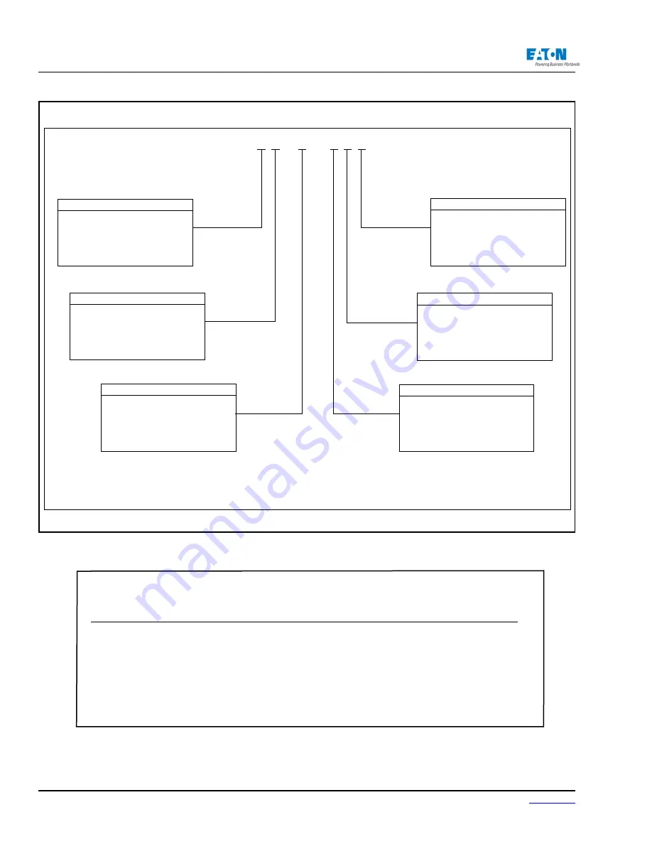
Power Xpert® Meter 4000/6000/8000 Catalog Numbering System
PXM 8
1
0 5
A
B
1 B
Card Slot 3 Con-gur ation
A
= No Card Option
B
= I/O Option Card
(8 Digital Inputs, 2
Solid State Outputs, 3 Relay Outputs)
Card Slot 2 Con-gur ation
A
= No Card Option
B
= Communication Expansion Card
w/100/1000Base-T, 100F, RS-485,
RS-232 Ports
Card Slot 1 Con-gur ation
1
= Standard Communications
Module with RS-485
Model Series
4
= 4000
(Standard Power Quality), 2GB
6
= 6000
(Enhanced Power Quality), 4GB
8
= 8000
(Premium PQ w/ Transient
Capture), 8GB
0
= Standard (V
1
, V
2
, V
3
, V
4
)
2
= Standard Plus Auxilary (V
6
, V
7
, V
8
)
Voltage Input Con-gur ation
1
= Standard 100-240 VAC or 110-250
VDC Power Supply
Voltage Input Con-gur ation
The example above represents a PXM8000 Meter, with Standard AC Power Configuration, and with a Communication Expan
-
sion Card and I/O Option Card.
Catalog Numbering System
Summary of Contents for Power Xpert PXM 4000
Page 1: ...User and Installation Manual IM02601004E Power Xpert PXM 4000 6000 8000 ...
Page 8: ...Page vi IM02601004E www eaton ...
Page 19: ...www eaton com IM02601004E Page 11 1 Introduction ...
Page 24: ...Page 16 IM02601004E www eaton ...
Page 36: ...Page 18 IM02601004E www eaton com 2 Quick Start Guide for the Meter Module ...
Page 45: ...www eaton com IM02601004E Page 37 3 Installation 3 8 MeterDimensions ...
Page 46: ...Page 38 IM02601004E www eaton 3 Installation Dimension Con t ...
Page 47: ...www eaton com IM02601004E Page 39 3 Installation Dimension Con t ...
Page 48: ...Page 40 IM02601004E www eaton 3 Installation Dimension Con t ...
Page 53: ...www eaton com IM02601004E Page 45 3 Installation ...
Page 54: ...Page 46 IM02601004E www eaton 3 Installation ...
Page 55: ...www eaton com IM02601004E Page 47 3 Installation ...
Page 56: ...Page 48 IM02601004E www eaton 3 Installation ...
Page 57: ...www eaton com IM02601004E Page 49 3 Installation ...
Page 58: ...Page 50 IM02601004E www eaton 3 Installation ...
Page 59: ...www eaton com IM02601004E Page 51 3 Installation ...
Page 60: ...Page 52 IM02601004E www eaton 3 Installation ...
Page 61: ...www eaton com IM02601004E Page 53 3 Installation ...
Page 62: ...Page 54 IM02601004E www eaton 3 Installation ...
Page 63: ...www eaton com IM02601004E Page 55 3 Installation ...
Page 66: ...Page 58 IM02601004E www eaton 3 Installation ...
Page 75: ...www eaton com IM02601004E Page 67 4 Introduction to Web Server Screens ...
Page 76: ...Page 68 IM02601004E www eaton 4 Introduction to Web Server Screens ...
Page 86: ...Page 78 IM02601004E www eaton 5 Introduction to the Local Graphical Display ...
Page 108: ...Page 100 IM02601004E www eaton 6 Functions on the Web Server Pages ...
Page 128: ...Page 120 IM02601004E www eaton 7 Functions on the Graphical Display ...
Page 164: ...Page 156 IM02601004E www eaton 8 Setup on the Web Server Pages ...
Page 198: ...Page 190 IM02601004E www eaton A MODBUS Communication ...
Page 242: ...Page 234 IM02601004E www eaton ...
Page 252: ...Page 244 IM02601004E www eaton D Diagnostics ...
Page 254: ...Page 246 IM02601004E www eaton D Diagnostics ...


