www.eaton.com
IM02601004E
Page 131
8 Setup on the Web Server Pages
Locating
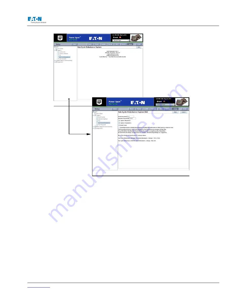
Subcycle
Disturbance Setup on the Web
From the Setup Main Page select Triggers from the tree structure on the left side of the page. The
tree structure will expand to list Out of Limits, Demand Overload, ITIC, Fast Transient and Subcycle
Disturbance. Click Subcycle Disturbance. The page will update to list current settings.
Use the Edit button at the bottom of the page to edit settings. When Edit is selected, the page will
display drop down boxes and check boxes for use in changing current settings. Click the Done but-
ton at the bottom of the page when entries are completed.
METER SETUP AND COMMISSIONING SETUP
The Meter Setup and Commissioning section of the Power Xpert Meter is broken into the following
categories: Security, Compensation, Metering, I/O, Clock, Communication and System. These cat-
egories contain setup information for Time of Use, PQ Index, Pulse Initiation, Hardware, Firmware,
etc. Security was discussed earlier in this section. The remainder of the pages in this category will
be discussed below.
COMPENSATION SETUP
The Compensation setup page allows you to compensate for errors within their PT and/or CT. The
value entered is used by the meter to multiply with respective to voltage and current channels. The
valid range is -10 to 10. A CT Compensation value with a negative sign could be used to reverse
the sign of measured current. This allows you to correct the polarity if the CT wires are incorrectly
Summary of Contents for Power Xpert PXM 4000
Page 1: ...User and Installation Manual IM02601004E Power Xpert PXM 4000 6000 8000 ...
Page 8: ...Page vi IM02601004E www eaton ...
Page 19: ...www eaton com IM02601004E Page 11 1 Introduction ...
Page 24: ...Page 16 IM02601004E www eaton ...
Page 36: ...Page 18 IM02601004E www eaton com 2 Quick Start Guide for the Meter Module ...
Page 45: ...www eaton com IM02601004E Page 37 3 Installation 3 8 MeterDimensions ...
Page 46: ...Page 38 IM02601004E www eaton 3 Installation Dimension Con t ...
Page 47: ...www eaton com IM02601004E Page 39 3 Installation Dimension Con t ...
Page 48: ...Page 40 IM02601004E www eaton 3 Installation Dimension Con t ...
Page 53: ...www eaton com IM02601004E Page 45 3 Installation ...
Page 54: ...Page 46 IM02601004E www eaton 3 Installation ...
Page 55: ...www eaton com IM02601004E Page 47 3 Installation ...
Page 56: ...Page 48 IM02601004E www eaton 3 Installation ...
Page 57: ...www eaton com IM02601004E Page 49 3 Installation ...
Page 58: ...Page 50 IM02601004E www eaton 3 Installation ...
Page 59: ...www eaton com IM02601004E Page 51 3 Installation ...
Page 60: ...Page 52 IM02601004E www eaton 3 Installation ...
Page 61: ...www eaton com IM02601004E Page 53 3 Installation ...
Page 62: ...Page 54 IM02601004E www eaton 3 Installation ...
Page 63: ...www eaton com IM02601004E Page 55 3 Installation ...
Page 66: ...Page 58 IM02601004E www eaton 3 Installation ...
Page 75: ...www eaton com IM02601004E Page 67 4 Introduction to Web Server Screens ...
Page 76: ...Page 68 IM02601004E www eaton 4 Introduction to Web Server Screens ...
Page 86: ...Page 78 IM02601004E www eaton 5 Introduction to the Local Graphical Display ...
Page 108: ...Page 100 IM02601004E www eaton 6 Functions on the Web Server Pages ...
Page 128: ...Page 120 IM02601004E www eaton 7 Functions on the Graphical Display ...
Page 164: ...Page 156 IM02601004E www eaton 8 Setup on the Web Server Pages ...
Page 198: ...Page 190 IM02601004E www eaton A MODBUS Communication ...
Page 242: ...Page 234 IM02601004E www eaton ...
Page 252: ...Page 244 IM02601004E www eaton D Diagnostics ...
Page 254: ...Page 246 IM02601004E www eaton D Diagnostics ...