6 - 8
Modulon DPH Series
6.2.2 Battery Mode Start-up Procedures
WARNING:
1. For parallel units, please follow
%\SDVV0RGH6WDUWXS3URFHGXUHV
to turn on each parallel UPS. After confirming that parallel operation works
normally, follow the procedures below step by step.
2. For parallel units, ensure that every operation procedure mentioned below is
synchronized to all parallel UPSs.
)RUSDUDOOHODSSOLFDWLRQLI\RXMXVWZDQWWRRSHUDWHDVSHFL¿F836EXWQRWDOO
parallel ones, please contact service personnel.
1
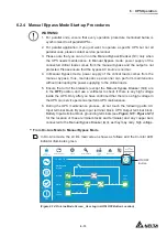
Ensure that the Manual Bypass Breaker (Q3) is in the
OFF
position.
2
Switch
ON
every external battery cabinet’s breaker (Q5).
3
Switch
ON
the Output Breaker (Q4).
4
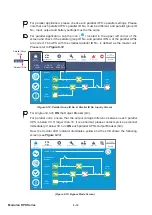
Press any of the
BATT. START
buttons (see
)LJXUH
) for one second and release
it. After that, each auxiliary power card’s LED indicator will illuminate green and the
following status will occur simultaneously.
(1) The system and each power module will start initialization. After each power
PRGXOH¿QLVKHVLQLWLDOL]DWLRQHDFKSRZHUPRGXOH¶VIDQVZLOOVWDUWUXQQLQJ
(2) Each parallel communication card’s LED indicator will illuminate red first and
then each card will start initialization. After initialization, the master parallel
communication card’s LED indicator will illuminate green and the backup
communication card’s LED indicator will illuminate yellow.
For the locations of the parallel communication cards, auxiliary power cards, power
modules and their LED indicators, please refer to
)LJXUH
.
5
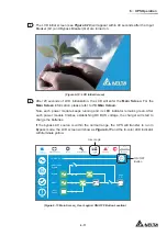
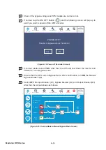
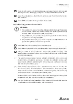
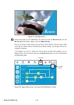
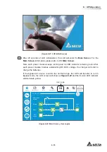
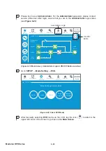
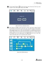
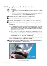
The LCD initial screen (see
)LJXUH
) will appear within 40 seconds after each
auxiliary power card’s LED indicator illuminates green.
)LJXUH/&',QLWLDO6FUHHQ
Summary of Contents for DPH-300K
Page 8: ......
Page 14: ......
Page 60: ......
Page 76: ......
Page 227: ...8 1 8 Optional Accessories 8 Optional Accessories ...
Page 230: ......
Page 231: ...9 1 9 Maintenance Maintenance ...
Page 233: ...A1 1 Appendix 1 7HFKQLFDO 6SHFL FDWLRQV Technical 6SHFL FDWLRQV A1 A1 ...
Page 236: ......
Page 237: ...A2 1 Appendix 2 Warranty Warranty A2 A2 ...
Page 240: ... ...


