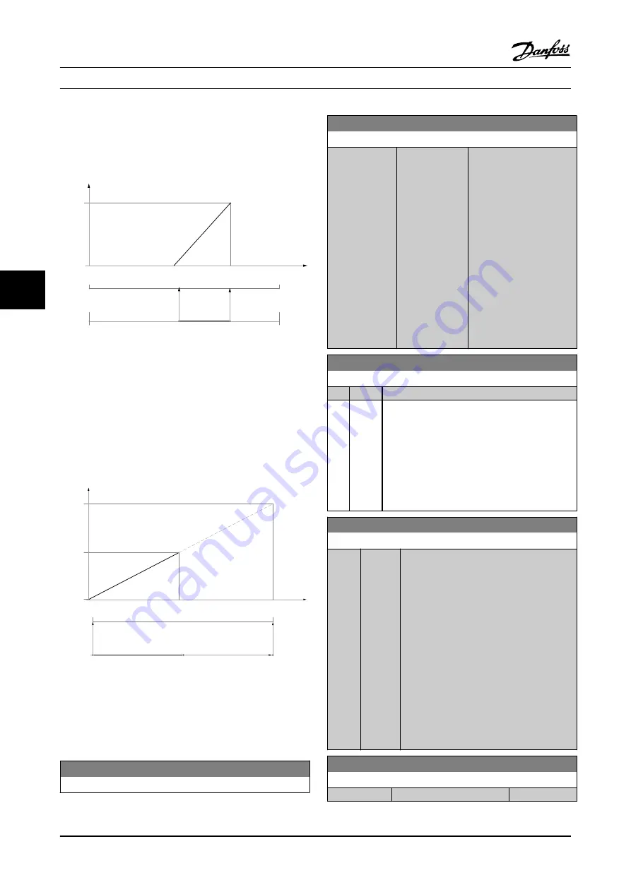
Output signal 0 or 4 mA is needed at 0% (50% of range) -
set
6-51 Terminal 42 Output Min Scale
to 50%
Output signal 20 mA is needed at 100% (75% of range) -
set
6-52 Terminal 42 Output Max Scale
to 75%
0/4 mA
20 mA
50%
75%
100%
0%
0%
+100%
+200%
-200%
130BA856.10
EXAMPLE 3:
Variable value= REFERENCE, range= Min ref - Max ref
Range needed for output= Min ref (0%) - Max ref (100%),
0–10 mA
Output signal 0 or 4 mA is needed at Min ref - set
6-51 Terminal 42 Output Min Scale
to 0%
Output signal 10 mA is needed at Max ref (100% of range)
- set
6-52 Terminal 42 Output Max Scale
to 200%
(20 mA / 10 mA x 100%=200%).
20 mA
10 mA
0/4 mA
100%
200%
0%
Max ref
Max ref X 20/10
Min ref
130BA857.10
6.2.7 Drive Closed-loop, 20-**
This parameter group is used for configuring the closed-
Loop PID controller that controls the output frequency of
the adjustable frequency drive.
20-12 Reference/Feedback Unit
Option:
Function:
20-21 Setpoint 1
Range:
Function:
0.000
ProcessCtrlUnit
*
[-999999.999 -
999999.999
ProcessCtrlUnit]
Setpoint 1 is used in
closed-loop mode to enter
a setpoint reference that is
used by the adjustable
frequency drive’s PID
controller. See the
description of
20-20 Feedback Function
.
NOTE!
Setpoint reference
entered here is added to
any other references
that are enabled (see
par. C-30 and par. C-34).
20-81 PID Normal/ Inverse Control
Option:
Function:
[0]
*
Normal
[1]
Inverse
Normal
[0] causes the adjustable frequency drive’s
output frequency to decrease when the feedback
is greater than the setpoint reference. This is
common for pressure-controlled supply fan and
pump applications.
Inverse
[1] causes the adjustable frequency drive’s
output frequency to increase when the feedback is
greater than the setpoint reference.
20-82 PID Start Speed [RPM]
Range:
Function:
0 RPM
*
[0 -
par. 4-13
RPM]
When the adjustable frequency drive is first
started, it initially ramps up to this output
speed in open-loop mode, following the
active ramp-up time. When the output speed
programmed here is reached, the adjustable
frequency drive will automatically switch to
closed-loop mode and the PID controller will
begin to function. This is useful in
applications in which the driven load must
first quickly accelerate to a minimum speed
when it is started.
NOTE!
This parameter will only be visible if
0-02 Motor Speed Unit
is set to [0], RPM.
20-93 PID Proportional Gain
Range:
Function:
0.50 N/A
*
[0.00 - 10.00 N/A]
How to program the adjustab...
VLT AQUA 12-Pulse High Power Instruction Manual
6-24
MG.20.Y1.22 - VLT
®
is a registered Danfoss trademark
6
6


