xStack® DGS-3120 Series Layer 3 Managed Gigabit Ethernet Switch Web UI Reference Guide
177
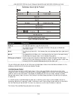
Figure 5-27 IP Tunnel GRE Settings (Edit) window
The fields that can be configured are described below:
Parameter
Description
Network Address
Enter the IPv4 network address assigned to the GRE tunnel interface. IPv4 processing
will be enabled on the IPv4 tunnel interface when an IPv4 address is configured. This
IPv4 address is not connected with the tunnel source or destination IPv4 address.
IPv6 Address/Prefix
Length
Enter the IPv6 network address assigned to the GRE tunnel interface. IPv6 processing
will be enabled on the IPv6 tunnel interface when an IPv6 address is configured. This
IPv6 address is not connected with the tunnel source or destination IPv4 address.
Source IPv4 Address
Click the radio button and enter the source IPv4 address of the GRE tunnel interface. It
is used as the source address for packets in the tunnel.
Source IPv6 Address
Click the radio button and enter the source IPv6 address of the GRE tunnel interface. It
is used as the source address for packets in the tunnel.
Destination IPv4
Address
Click the radio button and enter the destination IPv4 address of the GRE tunnel
interface. It is used as the destination address for packets in the tunnel.
Destination IPv6
Address
Click the radio button and enter the destination IPv6 address of the GRE tunnel
interface. It is used as the destination address for packets in the tunnel.
Click the
<<Back
button to return to the previous window.
Click the
Apply
button to accept the changes made for each individual section.
OSPF (RI Mode Only)
The Open Shortest Path First (OSPF) routing protocol uses a link-state algorithm to determine routes to network
destinations. A “link” is an interface on a router and the “state” is a description of that interface and its relationship
to neighboring routers. The state contains information such as the IP address, subnet mask, type of network the
interface is attached to, other routers attached to the network, etc. The collection of link-states is then collected in a
link-state database that is maintained by routers running OSPF.
OSPF specifies how routers will communicate to maintain their link-state database and defines several concepts
about the topology of networks that use OSPF.
To limit the extent of link-state update traffic between routers, OSPF defines the concept of Area. All routers within
an area share the exact same link-state database, and a change to this database once one router triggers an
update to the link-state database of all other routers in that area. Routers that have interfaces connected to more
than one area are called Border Routers and take the responsibility of distributing routing information between
areas.
One area is defined as Area 0 or the Backbone. This area is central to the rest of the network in that all other areas
have a connection (through a router) to the backbone. Only routers have connections to the backbone and OSPF is
structured such that routing information changes in other areas will be introduced into the backbone, and then
propagated to the rest of the network.
Summary of Contents for xStack DGS-3120 Series
Page 1: ......

