xStack® DGS-3120 Series Layer 3 Managed Gigabit Ethernet Switch Web UI Reference Guide
209
Click the
Edit
button to re-configure the selected entry.
Click the
Delete
button to remove the selected entry.
After clicking the
Edit
button, the following window will appear.
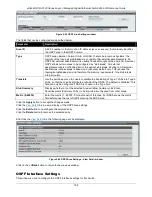
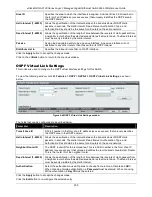
Figure 5-64 OSPFv3 Virtual Interface Settings - Edit window
The fields that can be configured are described below:
Parameter
Description
Hello Interval (1-65535)
Enter the interval time between the transmissions of OSPFv3 Hello packets, in
seconds. The Hello Interval and Dead Interval should be the same for all routers on
the same link. The default value is 10.
Dead Interval (1-65535)
Enter the interval time between the receipts of Hello packets from a neighbor router
before the selected area declares that router down. The Dead Interval must be
evenly divisible by the Hello Interval.
Instance ID (0-255)
Enter the instance ID of the interface. The default value is 0.
Click the
Apply
button to accept the changes made.
Click the
<<Back
button to return to the previous window.
OSPFv3 Area Aggregation Settings
This window is used to configure the OSPFv3 area aggregation settings.
To view the following window, click
L3 Features > OSPF > OSPFv3 > OSPFv3 Area Aggregation Settings
, as
shown below:
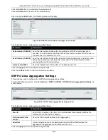
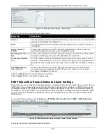
Figure 5-65 OSPFv3 Area Aggregation Settings window
The fields that can be configured are described below:
Parameter
Description
Area ID
Enter a 32-bit number in the form of an IPv4 address that uniquely identifies the
OSPFv3 area in the OSPFv3 domain.
IPv6 Address/Prefix
Length
Enter the IPv6 network address of the aggregation.
Advertise
Use the drop-down menu to specify whether the OSPFv3 ABR will use this
aggregation to aggregate the intra-area routes or not.
Click the
Apply
button to accept the changes made.
Summary of Contents for xStack DGS-3120 Series
Page 1: ......


