xStack® DGS-3120 Series Layer 3 Managed Gigabit Ethernet Switch Web UI Reference Guide
166
Hardware
Select the Hardware option to display only the routes that have been written into the
chip.
(RI and EI Mode Only)
Click the
Find
button to locate a specific entry based on the information entered.
Enter a page number and click the
Go
button to navigate to a specific page when multiple pages exist.
IPv6 Default Route Settings (SI Mode Only)
Entries into the Switch’s forwarding table can be made using both an IPv6 address and a gateway.
To view the following window, click
L3 Features > IPv6 Default Route Settings
, as shown below:
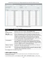
Figure 5-7 IPv6 Default Route Settings window
The fields that can be configured are described below:
Parameter
Description
Interface Name
The IP Interface where the default IPv6 route is created.
Nexthop Address
The corresponding IPv6 address for the next hop gateway address in IPv6 format.
Metric (1-65535)
Represents the metric value of the IPv6 interface entered into the table. This field may
read a number between 1 and 65535.
Backup State
Specify the backup state of the default route created. Options to choose from are
Primary
and
Backup
.
Click the
Apply
button to accept the changes made.
Click the
Delete
button to delete the corresponding entry.
Click the
Delete All
button to remove all the entries listed.
Enter a page number and click the
Go
button to navigate to a specific page when multiple pages exist.
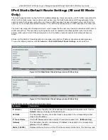
IPv6 Static/Default Route Settings (RI and EI Mode
Only)
A static entry of an IPv6 address can be entered into the Switch’s routing table for IPv6 formatted addresses.
To view the following window, click
L3 Features > IPv6 Static/Default Route Settings
, as shown below:
Summary of Contents for xStack DGS-3120 Series
Page 1: ......


