C200H AC Servo Manual
25
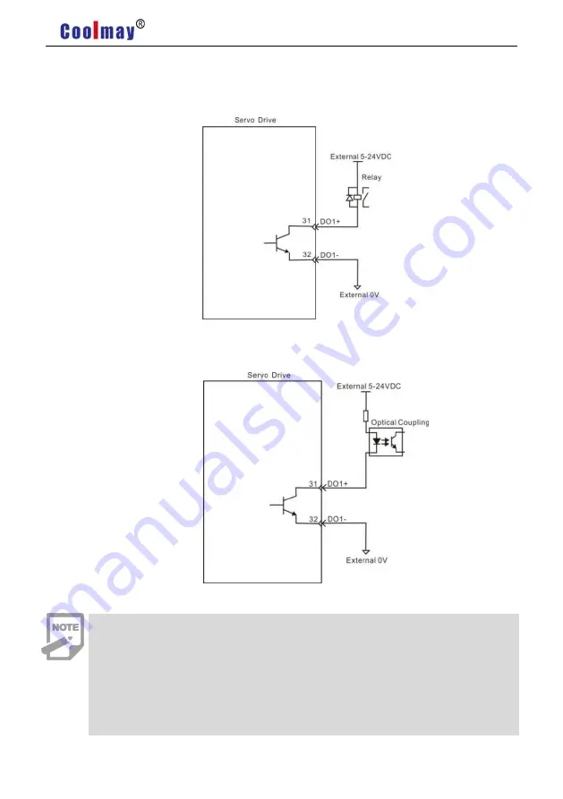
Output Circuit Of Digital Quantity Diagram
For DO1 as an example( the DO1~DO6 interface circuit is the same)
:
1)
When the upper device is relay input
:
2) When the upper device is optocoupler input:
Be sure to connect a continuation diode when the upper device is a relay,
otherwise it may damage DO ports or cause strong signal interference.
The maximum allowable voltage and current capacity of the optocoupler
output circuit in the servo drive are as follows:
Voltage
:
DC30V
Current
:
DC50mA
Summary of Contents for C200H Series
Page 1: ...https en coolmay com ...
Page 2: ...C200H AC Servo Manual https en coolmay com ...
Page 43: ...C200H AC Servo Manual 36 Pic 4 17 Ground Connection Handling Of Noise Filter ...
Page 52: ...C200H AC Servo Manual 45 5 2 2 Speed Mode Wiring 三相 Pic5 4 Speed Mode Wiring ...
Page 55: ...C200H AC Servo Manual 48 5 3 2 Torque Mode Wiring Pic5 6 Torque Mode Wiring ...


