C200H AC Servo Manual
16
4.3.2 Regeneration Resistance Connection
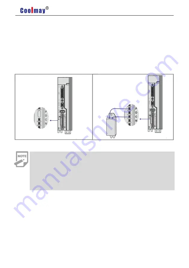
If use the built-in resistor, please connect P and D( a 4 pins connector for built-in resistor
has been set by factory, so you can insert it to the terminal directly), as picture A showed.
When an external regeneration resistance is connected to the servo drive, the short circuit
between terminal P and D must be disconnected. Then the external regeneration resistance could
be connected between P and C, and leave N alone,as picture B showed.
Pic A
Pic B
Precautions for braking resistance wiring:
Do not connect the external brake resistance to the positive and negative
poles of the bus P
、
N, otherwise it will cause explosion and fire.
Must be over minimum resistance value at 25Ω. Otherwise it would cause
drive alarm or damage.
Please install external brake resistance on non-combustible materials such as
metal.
Summary of Contents for C200H Series
Page 1: ...https en coolmay com ...
Page 2: ...C200H AC Servo Manual https en coolmay com ...
Page 43: ...C200H AC Servo Manual 36 Pic 4 17 Ground Connection Handling Of Noise Filter ...
Page 52: ...C200H AC Servo Manual 45 5 2 2 Speed Mode Wiring 三相 Pic5 4 Speed Mode Wiring ...
Page 55: ...C200H AC Servo Manual 48 5 3 2 Torque Mode Wiring Pic5 6 Torque Mode Wiring ...


