


+3.3V/+1.5V circuit .......................................................................2-32
Reset circuit ..................................................................................2-33
Clock circuit ..................................................................................2-33
Ope-pane circuit............................................................................2-34
USB I/F control circuit ...................................................................2-34
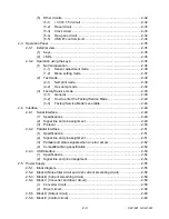
Sensor adjustment mode..............................................................2-36
Menu setting mode .......................................................................2-37
Self print mode..............................................................................2-38
Hex dump mode ...........................................................................2-39
How to enter the Factory/Service Mode........................................2-40
Factory/Service Mode menu table ................................................2-44
Parallel port status signals when an error occurs ......................................2-52
Signal line and pin arrangement ................................................................2-54
Block A (Noise filter circuit and rush current preventing circuit)..........................2-58
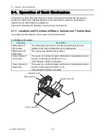
2-3
CLP-621 & CLP-631
Summary of Contents for CLP-621
Page 1: ...Technical Manual CLP 621 CLP 631 Thermal Transfer Barcode Label Printer JM74961 00F 1 00E 0701...
Page 2: ...CLP 621 CLP 631 ii Copyright 2007 by CITIZEN SYSTEMS JAPAN CO LTD...
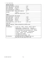
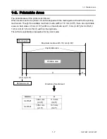
Page 4: ...CHAPTER 1 SPECIFICATIONS CLP 621 CLP 631...
Page 13: ...CHAPTER 2 OPERATING PRINCIPLES CLP 621 CLP 631...
Page 73: ...CHAPTER 3 DISASSEMBLY AND MAINTENANCE CLP 621 CLP 631...
Page 126: ...CLP 621 CLP 631 CHAPTER 4 TROUBLESHOOTING...
Page 138: ...CLP 621 CLP 631 CHAPTER 5 PARTS LISTS...
Page 166: ...Chapter 5 Parts Lists CLP 621 CLP 631 5 29 DRAWING NO 7 Control Panel Unit Rev 0 4 3 2 1 5...
Page 177: ...Chapter 5 Parts Lists CLP 621 CLP 631 5 40 DRAWING NO 10 Accessories Rev 0 3 2 4 1...
Page 179: ...CHAPTER 6 CIRCUIT DIAGRAMS CLP 621 CLP 631...
Page 208: ...APPENDICES CLP 621 CLP 631...
Page 212: ...B Mounting Diagrams AP 5 CLP 621 CLP 631 Main PCB Solder side...
Page 214: ...B Mounting Diagrams AP 7 CLP 621 CLP 631 B 3 Ribbon Main PCB Parts side Solder side...
Page 217: ......


