


2-4. Interface
CLP-621 & CLP-631
2-50
(3) Protocol
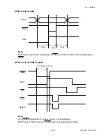
XON/XOFF system:
Controlled with the data transmission request signal X-ON (11H) code and the data
transmission stop request signal X-OFF (13H) code.
The conditions for the X-ON code output are as follows:
•
When the printer is turned from off-line to on-line.
• When the remaining of receive buffer is 1024 bytes or more after sending X-OFF code.
The conditions for the X-OFF code output are as follows:
• When the remainder of receive buffer is 128 bytes or less.
• When the printer is turned from on-line to off-line.
- When the media end is detected.
- When a printer error occurs.
X-ON code sending
X-OFF code sending
16K bytes
1024 bytes
128 bytes
Received data
0
16K
READY/BUSY System:
DTR signal is controlled with READY ("High")/BUSY ("Low") level.
DTR turns to "High (Ready)" in the following conditions:
• When the printer is in on-line mode, and
• When the remaining buffer is 128 bytes or more.
(After DTR becomes "High", DTR retains "High" until the remaining buffer becomes 1024
bytes or less.)
DTR turns to "Low (Busy)" in the following conditions:
• When the printer is in off-line mode.
• When the remaining buffer is less than 128 bytes.
(After DTR becomes "Low", DTR retains "Low" until the remaining buffer becomes 1024 bytes
or more.)
Summary of Contents for CLP-621
Page 1: ...Technical Manual CLP 621 CLP 631 Thermal Transfer Barcode Label Printer JM74961 00F 1 00E 0701...
Page 2: ...CLP 621 CLP 631 ii Copyright 2007 by CITIZEN SYSTEMS JAPAN CO LTD...
Page 4: ...CHAPTER 1 SPECIFICATIONS CLP 621 CLP 631...
Page 13: ...CHAPTER 2 OPERATING PRINCIPLES CLP 621 CLP 631...
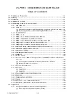
Page 73: ...CHAPTER 3 DISASSEMBLY AND MAINTENANCE CLP 621 CLP 631...
Page 126: ...CLP 621 CLP 631 CHAPTER 4 TROUBLESHOOTING...
Page 138: ...CLP 621 CLP 631 CHAPTER 5 PARTS LISTS...
Page 166: ...Chapter 5 Parts Lists CLP 621 CLP 631 5 29 DRAWING NO 7 Control Panel Unit Rev 0 4 3 2 1 5...
Page 177: ...Chapter 5 Parts Lists CLP 621 CLP 631 5 40 DRAWING NO 10 Accessories Rev 0 3 2 4 1...
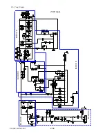
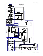
Page 179: ...CHAPTER 6 CIRCUIT DIAGRAMS CLP 621 CLP 631...
Page 208: ...APPENDICES CLP 621 CLP 631...
Page 212: ...B Mounting Diagrams AP 5 CLP 621 CLP 631 Main PCB Solder side...
Page 214: ...B Mounting Diagrams AP 7 CLP 621 CLP 631 B 3 Ribbon Main PCB Parts side Solder side...
Page 217: ......


