


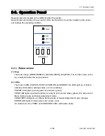


2-2. Operation of Control Parts
2-27
CLP-621 & CLP-631
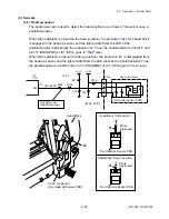
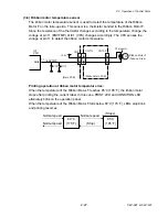
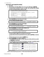
(3-6) Ribbon motor temperature sensor
The ribbon motor temperature sensor is used to detect the temperature of the Ribbon
Motor F on the take-up side. This sensor is a thermistor bonded to the Ribbon Motor F.
Since the resistance of the thermistor changes according to the temperature change, the
voltage at pin 11 (ENVTMP) of IC1 (CPU) changes accordingly. The CPU senses the
voltage at pin 11 to detect the ribbon motor temperature.
5
CN702
M
Ribbon Motor F
(Take-up Side)
6
Thermistor
R113
C73
IC1
CPU
[Ribbon Main PCB]
ENVTMP
ANI6
11
9
CN701
20
+3.3V
1
12
CN8
[Main PCB]
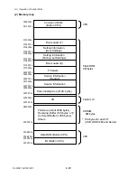
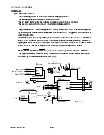
Printing operation at ribbon motor temperature rise:
When the temperature of the Ribbon Motor F reaches 85
°
C (185
°
F), the ribbon motor
stops after printing the current label. In this case, PRINT LED and CONDITION LED
alternately blink on the operation panel.
When the temperature of the Ribbon Motor F falls below 80
°
C (176
°
F), LEDs stop blink
and printing resumes.
80
°
C
(176
°
F)
85
°
C
(185
°
F)
Normal speed
(Stop)
Normal speed
Normal speed
(Stops)
Summary of Contents for CLP-621
Page 1: ...Technical Manual CLP 621 CLP 631 Thermal Transfer Barcode Label Printer JM74961 00F 1 00E 0701...
Page 2: ...CLP 621 CLP 631 ii Copyright 2007 by CITIZEN SYSTEMS JAPAN CO LTD...
Page 4: ...CHAPTER 1 SPECIFICATIONS CLP 621 CLP 631...
Page 13: ...CHAPTER 2 OPERATING PRINCIPLES CLP 621 CLP 631...
Page 73: ...CHAPTER 3 DISASSEMBLY AND MAINTENANCE CLP 621 CLP 631...
Page 126: ...CLP 621 CLP 631 CHAPTER 4 TROUBLESHOOTING...
Page 138: ...CLP 621 CLP 631 CHAPTER 5 PARTS LISTS...
Page 166: ...Chapter 5 Parts Lists CLP 621 CLP 631 5 29 DRAWING NO 7 Control Panel Unit Rev 0 4 3 2 1 5...
Page 177: ...Chapter 5 Parts Lists CLP 621 CLP 631 5 40 DRAWING NO 10 Accessories Rev 0 3 2 4 1...
Page 179: ...CHAPTER 6 CIRCUIT DIAGRAMS CLP 621 CLP 631...
Page 208: ...APPENDICES CLP 621 CLP 631...
Page 212: ...B Mounting Diagrams AP 5 CLP 621 CLP 631 Main PCB Solder side...
Page 214: ...B Mounting Diagrams AP 7 CLP 621 CLP 631 B 3 Ribbon Main PCB Parts side Solder side...
Page 217: ......


