


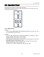


2-2. Operation of Control Parts
CLP-621 & CLP-631
2-22
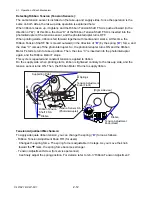
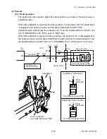
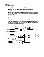
(3-2) Transparent sensor and reflective sensor
The transparent sensor is used to detect the label stuck on liner and the U-shaped notch
on tag. While, the reflective sensor is used to detect the black mark printed on the bottom
surface of tag. Both sensors are also used to detect the media end.
The upper side transparent sensor is the phototransistor, and the lower side reflective
sensor consists of 2 LEDs and 1 phototransistor. Media passes between these sensors.
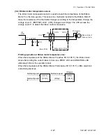
Transparent sensor (used for detecting the label or U-shaped notch):
When the liner without label stuck on it passes between both sensors, the light emitted
from the LEDs reaches the transparent sensor, passing through the liner. Thus, the
transparent sensor (phototransistor) conducts and the voltage corresponding to the
amount of light is applied to pin 5 (TRANMON) of IC1 (CPU).
Meanwhile, when the liner with the label stuck on it passes between both sensors, the light
is blocked by the label and the transparent sensor (phototransistor) turns OFF. Thus, pin 5
(REFMON) of IC1 (CPU) goes "Low" level. From these levels, IC1 (CPU) can detect the
leading edge (arrival) of the label on liner.
When media runs out, the light directly falls on the transparent sensor and media end is
detected. In this case, pin 5 of IC1 (CPU) will go "High" level.
The current flowing into the LEDs is determined by the data sent from the CPU to the
digital-to-analog converter (IC4). The digital-to-analog converter converts the data received
from the CPU and outputs resoultant level at pin 7. The base current of the transistor TR4
is determined by this level. This means that the current flowing into the LEDs is also
determined by this level. In the actual control, the CPU changes data (LED current) to
keep the level at pin 5 of CPU constant.
Summary of Contents for CLP-621
Page 1: ...Technical Manual CLP 621 CLP 631 Thermal Transfer Barcode Label Printer JM74961 00F 1 00E 0701...
Page 2: ...CLP 621 CLP 631 ii Copyright 2007 by CITIZEN SYSTEMS JAPAN CO LTD...
Page 4: ...CHAPTER 1 SPECIFICATIONS CLP 621 CLP 631...
Page 13: ...CHAPTER 2 OPERATING PRINCIPLES CLP 621 CLP 631...
Page 73: ...CHAPTER 3 DISASSEMBLY AND MAINTENANCE CLP 621 CLP 631...
Page 126: ...CLP 621 CLP 631 CHAPTER 4 TROUBLESHOOTING...
Page 138: ...CLP 621 CLP 631 CHAPTER 5 PARTS LISTS...
Page 166: ...Chapter 5 Parts Lists CLP 621 CLP 631 5 29 DRAWING NO 7 Control Panel Unit Rev 0 4 3 2 1 5...
Page 177: ...Chapter 5 Parts Lists CLP 621 CLP 631 5 40 DRAWING NO 10 Accessories Rev 0 3 2 4 1...
Page 179: ...CHAPTER 6 CIRCUIT DIAGRAMS CLP 621 CLP 631...
Page 208: ...APPENDICES CLP 621 CLP 631...
Page 212: ...B Mounting Diagrams AP 5 CLP 621 CLP 631 Main PCB Solder side...
Page 214: ...B Mounting Diagrams AP 7 CLP 621 CLP 631 B 3 Ribbon Main PCB Parts side Solder side...
Page 217: ......


