


3-5. Disassembly, Reassembly and Lubrication
3-15
CLP-621 & CLP-631
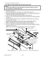
3-5-7. Ribbon Sensor F/R Unit and Ribbon Unit Base Plate SA1
Caution:
DO NOT disassemble the Ribbon Unit Base Plate SA1, though it consists of three parts.
If it is disassembled, correct ribbon running cannot be assured. Namely, ribbon slant
correction may become impossible within the adjustable range of the Ribbon Left-Right
Balance Adjustment Knobs (Front/Rear).
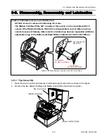
1. Open the Top Cover SA.
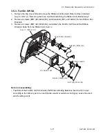
2. Remove 4 screws (NO.0, TFH, M2x3 (NI)) and detach the Ribbon Tension Adjust Covers on
the front and rear sides.
3. Remove 2 screws (BH, M3x3 (NI)) and detach the Ribbon Sensor F Unit.
4. Remove 2 screws (BH, M3x3 (NI)) and detach the Ribbon Sensor R Unit.
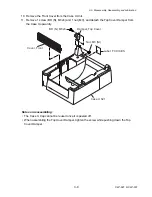
5. Remove 2 screws (PH, M3x6) and detach the Ribbon Unit Base Plate SA1 from the
Mechanism Unit.
(Ribbon Sensor F Unit)
BH, M3x3 (NI)
Cover, Ribbon Tension Adjust
(Ribbon Sensor R Unit)
BH, M3x3 (NI)
NO.0, TFH, M2x3 (NI)
NO.0, TFH, M2x3 (NI)
SA1, Ribbon Unit Base Plate
PH, M3x6
Note on reassembling:
• When assembling the Ribbon Sensor F/R Unit, perform 3-6-2 “Ribbon Slant Elimination
Adjustment” on page
3-45.
Summary of Contents for CLP-621
Page 1: ...Technical Manual CLP 621 CLP 631 Thermal Transfer Barcode Label Printer JM74961 00F 1 00E 0701...
Page 2: ...CLP 621 CLP 631 ii Copyright 2007 by CITIZEN SYSTEMS JAPAN CO LTD...
Page 4: ...CHAPTER 1 SPECIFICATIONS CLP 621 CLP 631...
Page 13: ...CHAPTER 2 OPERATING PRINCIPLES CLP 621 CLP 631...
Page 73: ...CHAPTER 3 DISASSEMBLY AND MAINTENANCE CLP 621 CLP 631...
Page 126: ...CLP 621 CLP 631 CHAPTER 4 TROUBLESHOOTING...
Page 138: ...CLP 621 CLP 631 CHAPTER 5 PARTS LISTS...
Page 166: ...Chapter 5 Parts Lists CLP 621 CLP 631 5 29 DRAWING NO 7 Control Panel Unit Rev 0 4 3 2 1 5...
Page 177: ...Chapter 5 Parts Lists CLP 621 CLP 631 5 40 DRAWING NO 10 Accessories Rev 0 3 2 4 1...
Page 179: ...CHAPTER 6 CIRCUIT DIAGRAMS CLP 621 CLP 631...
Page 208: ...APPENDICES CLP 621 CLP 631...
Page 212: ...B Mounting Diagrams AP 5 CLP 621 CLP 631 Main PCB Solder side...
Page 214: ...B Mounting Diagrams AP 7 CLP 621 CLP 631 B 3 Ribbon Main PCB Parts side Solder side...
Page 217: ......


