


CLP-621 & CLP-631
5-2
CHAPTER 5 PARTS LISTS
TABLE OF CONTENTS
Mechanical Section
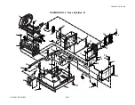
General Assembly (Drawing No. 1)................................................................................. 5-5
Base Unit (Drawing No. 2) .............................................................................................. 5-8
Mechanism Unit (Drawing No. 3) .................................................................................... 5-13
Head-TT Unit (Drawing No. 4) ........................................................................................ 5-17
PF Unit (Drawing No. 5).................................................................................................. 5-21
Sensor U Unit (Drawing No. 6) ....................................................................................... 5-25
Control Panel Unit (Drawing No. 7)................................................................................. 5-28
Ribbon Unit (Drawing No. 8) ........................................................................................... 5-31
Ribbon Unit Fan SA2 (Drawing No. 9) ............................................................................ 5-36
Accessories (Drawing No. 10) ........................................................................................ 5-39
Summary of Contents for CLP-621
Page 1: ...Technical Manual CLP 621 CLP 631 Thermal Transfer Barcode Label Printer JM74961 00F 1 00E 0701...
Page 2: ...CLP 621 CLP 631 ii Copyright 2007 by CITIZEN SYSTEMS JAPAN CO LTD...
Page 4: ...CHAPTER 1 SPECIFICATIONS CLP 621 CLP 631...
Page 13: ...CHAPTER 2 OPERATING PRINCIPLES CLP 621 CLP 631...
Page 73: ...CHAPTER 3 DISASSEMBLY AND MAINTENANCE CLP 621 CLP 631...
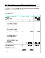
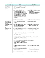
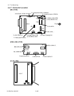
Page 126: ...CLP 621 CLP 631 CHAPTER 4 TROUBLESHOOTING...
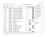
Page 138: ...CLP 621 CLP 631 CHAPTER 5 PARTS LISTS...
Page 166: ...Chapter 5 Parts Lists CLP 621 CLP 631 5 29 DRAWING NO 7 Control Panel Unit Rev 0 4 3 2 1 5...
Page 177: ...Chapter 5 Parts Lists CLP 621 CLP 631 5 40 DRAWING NO 10 Accessories Rev 0 3 2 4 1...
Page 179: ...CHAPTER 6 CIRCUIT DIAGRAMS CLP 621 CLP 631...
Page 208: ...APPENDICES CLP 621 CLP 631...
Page 212: ...B Mounting Diagrams AP 5 CLP 621 CLP 631 Main PCB Solder side...
Page 214: ...B Mounting Diagrams AP 7 CLP 621 CLP 631 B 3 Ribbon Main PCB Parts side Solder side...
Page 217: ......


