


2-2. Operation of Control Parts
2-33
CLP-621 & CLP-631
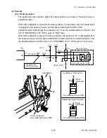
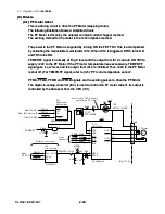
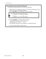
(5-2) Reset circuit
This circuit performs the system reset.
When the power is turned ON, +3.3V (VCC) gradually increases from 0V. When the
voltage at pin 5 (+3.3V) of IC3 reaches a certain level, IC3 is activated and the RESET
signal changes from "Low" to "High" level. While the RESET signal is “Low”, the CPU (IC1)
is reset. When the power is turned OFF and +3.3V drops below a certain level, the RESET
signal changes from "High" to "Low" level, and the CPU is reset.
The CPU outputs the GRESET signals to reset the Custom IC (IC11) and other ICs.
GND
+3.3V
3
4
1
Voltage Detector
RESET
RESET
L : Reset
26
IC1
CPU
RESET
IC11
Custom IC
Power ON
Reset
+3.3V
RESET
+3.3V
H
L
0V
P52
GRESET
GRESET
Pin 1 of IC3
IC3
BD5328FVE
P17
C3
T4
RESET
Vout
CT
SUB
2
VDD
5
28
23
C4
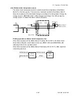
(5-3) Clock circuit
Crystal oscillator Y1 oscillates a 16 MHz clock. This clock is send to the CPU (IC1) and the
CPU generates a 128 MHz internal clock and 64 MHz clock.
The 64MHz clock is fed to the Custom IC (IC11).
Oscillator Y2 oscillates a 48 MHz clock used for USB I/F control. It starts oscillation when
UCLKON signal (pin 77) is output from the CPU to Y2.
IC1
CPU
IC11
Custom IC
Y1
R1
C2
System Clock
(16MHz)
P2
P3
BUSCLK
PCD1 88
P132
CLKIN
119
GND
+3.3V
Clock Generator
Clock for USB
(48MHz)
UCLKON
PCT7
Y2
VDD
T1
UCLK
P8
FCXO-03 (48MHz)
STBY
OUT
P20
UCLKON 77
Bus Clock
(64MHz)
Internal Clock
(128MHz)
P10
159
C1
R17
BUSCLK
[Main PCB]
R2
FCX-03 (16MHz)
X1
164
X2
165
Summary of Contents for CLP-621
Page 1: ...Technical Manual CLP 621 CLP 631 Thermal Transfer Barcode Label Printer JM74961 00F 1 00E 0701...
Page 2: ...CLP 621 CLP 631 ii Copyright 2007 by CITIZEN SYSTEMS JAPAN CO LTD...
Page 4: ...CHAPTER 1 SPECIFICATIONS CLP 621 CLP 631...
Page 13: ...CHAPTER 2 OPERATING PRINCIPLES CLP 621 CLP 631...
Page 73: ...CHAPTER 3 DISASSEMBLY AND MAINTENANCE CLP 621 CLP 631...
Page 126: ...CLP 621 CLP 631 CHAPTER 4 TROUBLESHOOTING...
Page 138: ...CLP 621 CLP 631 CHAPTER 5 PARTS LISTS...
Page 166: ...Chapter 5 Parts Lists CLP 621 CLP 631 5 29 DRAWING NO 7 Control Panel Unit Rev 0 4 3 2 1 5...
Page 177: ...Chapter 5 Parts Lists CLP 621 CLP 631 5 40 DRAWING NO 10 Accessories Rev 0 3 2 4 1...
Page 179: ...CHAPTER 6 CIRCUIT DIAGRAMS CLP 621 CLP 631...
Page 208: ...APPENDICES CLP 621 CLP 631...
Page 212: ...B Mounting Diagrams AP 5 CLP 621 CLP 631 Main PCB Solder side...
Page 214: ...B Mounting Diagrams AP 7 CLP 621 CLP 631 B 3 Ribbon Main PCB Parts side Solder side...
Page 217: ......


