


2-1. Operation of Each Mechanism
2-1. Operation of Each Mechanism
This printer is a thermal transfer barcode & printer comprised of the following mechanisms:
media feed, ribbon feed, label/tag detection, print head up/down detection, head balance
adjustment and media thickness adjustment.
This section describes the operation of each of these mechanisms.
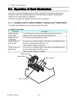
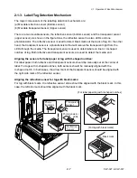
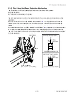
2-1-1. Locations and Functions of Motors, Sensors and Thermal Head
This printer has the following motors, sensors and thermal head.
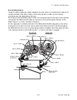
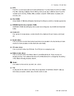
(1) Ribbon unit section
Part name
Description
Ribbon Motor F
(Front side)
This motor takes up ribbon. A thermistor is attached to the side
surface of this motor to detect the motor temperature.
Ribbon Motor R
(Rear side)
This motor gives back tension to ribbon.
Tension Sensor F
(Front side)
This sensor is a photointerrupter which detects if appropriate tension
is given to the take-up side ribbon or not.
It also detects a ribbon-running error.
Tension Sensor R
(Rear side)
This sensor is a photointerrupter which detects if appropriate tension
is given to the supply side ribbon or not.
It also detects the ribbon end status.
Tension Sensor R
Ribbon Motor R
Ribbon Motor F
Tension Sensor F
CLP-621 & CLP-631
2-4
Summary of Contents for CLP-621
Page 1: ...Technical Manual CLP 621 CLP 631 Thermal Transfer Barcode Label Printer JM74961 00F 1 00E 0701...
Page 2: ...CLP 621 CLP 631 ii Copyright 2007 by CITIZEN SYSTEMS JAPAN CO LTD...
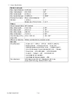
Page 4: ...CHAPTER 1 SPECIFICATIONS CLP 621 CLP 631...
Page 13: ...CHAPTER 2 OPERATING PRINCIPLES CLP 621 CLP 631...
Page 73: ...CHAPTER 3 DISASSEMBLY AND MAINTENANCE CLP 621 CLP 631...
Page 126: ...CLP 621 CLP 631 CHAPTER 4 TROUBLESHOOTING...
Page 138: ...CLP 621 CLP 631 CHAPTER 5 PARTS LISTS...
Page 166: ...Chapter 5 Parts Lists CLP 621 CLP 631 5 29 DRAWING NO 7 Control Panel Unit Rev 0 4 3 2 1 5...
Page 177: ...Chapter 5 Parts Lists CLP 621 CLP 631 5 40 DRAWING NO 10 Accessories Rev 0 3 2 4 1...
Page 179: ...CHAPTER 6 CIRCUIT DIAGRAMS CLP 621 CLP 631...
Page 208: ...APPENDICES CLP 621 CLP 631...
Page 212: ...B Mounting Diagrams AP 5 CLP 621 CLP 631 Main PCB Solder side...
Page 214: ...B Mounting Diagrams AP 7 CLP 621 CLP 631 B 3 Ribbon Main PCB Parts side Solder side...
Page 217: ......


